

Alarm management has become a subject of interest in many plants. With the advent of computerised control and HMI systems, it has become extremely easy to put alarms onto control loops. Nowadays operators are often subjected to a surfeit of alarms and as a result they eventually tend to ignore most of them, since it is often hard for them to determine which alarms are really serious.
A refinery in which I recently optimised some control loops decided to institute a study of the alarms and rationalise them. Part of the study was to identify the ones that occurred most commonly and try and improve the controls to stop alarms occurring frequently under normal process conditions. The loops producing these alarms are termed ‘bad actors’.
Example 1
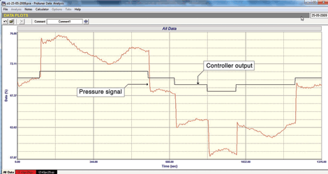
The first example was of a pressure loop which had been optimised properly in 2009. Figure 1 shows the original open loop test which was performed at that time for analysis and tuning. Although the test indicates that the pressure tends to vary around quite a bit with a constant controller output, the variations are probably due to other loops interacting with it. It should be noted that equal size steps in PD (controller output) produced steps on the PV which were also equal in magnitude. This indicates that the valve had linear installed characteristics. The very large steps on the PV produced by relatively small steps on the PD would indicate that the valve was largely oversized.
In 2012 the loop was classified as a bad actor as it gave rise to numerous alarms. It was retuned and worked well for a while and then started playing up again. This happened several times and we were asked to investigate why it needed constant retuning.
The problem with non-linear characteristics
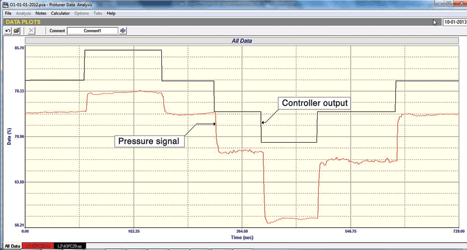
Figure 2, one of the later open loop tests performed in 2013, gives the answer. It can be seen that the dynamics of the process have changed drastically from those of the process at the time of the test in 2009. Seeing that the process itself had not changed, it was obvious that the valve had been replaced. This was the first reason that the tuning no longer worked properly. The second thing that can be seen from the test is that although steps of equal magnitude were being made on the PD, the size of the responding steps on the PV changed dramatically in size over the relatively small measurement range where the test was performed. This shows that the valve has very non-linear installed characteristics.
When you tune a controller, you are matching the dynamic characteristics of the controller to those of the process. These characteristics are typically obtained from an open loop step test. If the process’s dynamic characteristics change then the tuning will no longer work. This is the problem with non-linear installed valve characteristics, particularly if you are working at differing set-points over the measuring range. You tune at one place and it works well, then if you change the set-point, for example to a higher value, the control response will change. In the case of this loop, if for example you tune at one place, then the response will get slower and slower the higher you go from there, and vice-versa it will get faster as you move down, and may even go unstable.
The first thing that needs doing in this case is to linearise the characteristics, which is usually best done in these days of smart positioners by fitting a correctly compensating characteristic curve into the positioner. I am sure that once this has been done and the controller retuned, the loop will be removed from the list of bad actors.
Example 2
The second example of a bad actor was a slow level loop that was in a continuous cycle with the valve fully opening and closing during the cycle.
Level loops are integrating processes and are notorious for their tendency to cycle. Furthermore, very few C&I practitioners really understand the practicalities of integrating processes and have very little idea on how to tune them.
The problem with integrating processes
The two main reasons why these processes tend to cycle are due to bad tuning or if the valve in the loop has hysteresis on it. Also, a contributing factor that exacerbates the cycling of an integrating process is the integral term in the controller. The purpose of integral is to eliminate control error and get the process to set-point. It is a very powerful factor in control action and normally does a great job. However, if for whatever reason it cannot eliminate error, then the integral never gives up and keeps on pushing the controller output. This leads to problems in control such as reset (integral) windup which can lock-up loops for long periods and cause big overshoots when coming back into control. It also is a major contributor to the cyclic nature of integrating processes.
Integrating processes are in fact better off without the I term in the controller. Apart from dramatically lessening the tendency of these processes to cycle, the control is actually better. (The reason for this is beyond the scope of this article.) Unfortunately if the I term is not used, one will almost certainly end up with offset in the control, i.e. the process will settle out away from set-point. This is generally unacceptable in most controls and operators get very unhappy if processes do not ever get to set-point.
The main characteristics of an integrating process are that it has internal capacity and its input and output can differ for long periods. For example, in a level process the level will rise and fall if the input and output flows are not the same. However if they are equal then the level remains constant. Thus the main thing when controlling such a process is to balance the input and output flows when the desired level is attained. This differs from the more common self-regulating type of process like a flow, where if you change the input the output will also change to equal the input flow.
The open loop analytical and tuning test one performs on an integrating process (like a level process in manual) is started when the input and output flows are balanced. A step change is then made on one of them and the dynamics of the process can be determined from this test, one can then do a tune.
Generally, to get such a process into balance, the easiest method is to switch off the I term (and D term if it has been used). With a P only control the system is now equivalent to a ball valve which normally finds its own balance. However, in this case it just went on cycling. We tried all sorts of things to no avail. As a last resort, took the controller out of auto and tried to find the balance point manually. Still no joy – the level just moved up or down.
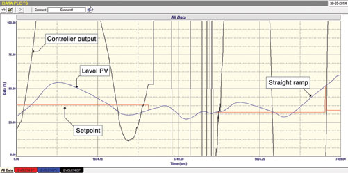
This went on for about a day, without being able to get the level to stay stable. One of the last tests is shown in Figure 3. It was seen on reviewing it that near the end with the PV level dropping, the PD had gone to zero and then the PV started ramping in a very linear fashion.
Now to tune an integrating process one needs to be able to measure the slope of the constant ramp and then divide it by the size of the PD step that caused it. We had the slope but not the size of PD step, but it was a starting point to calculate the tuning. We guessed at various PD step sizes that seemed reasonable and then tried a tune. To our amazement it worked reasonably well, and for the first time using that tuning and putting the controller into automatic, we managed to stabilise the level, and get some control!
Figure 4 shows a section of the test with the controller in automatic. It can be seen that the controller is really working hard to deal with continuous load disturbances, but the control is pretty good considering the haphazard tuning. It should also be noted that the controller is working pretty close to the top which could indicate that the valve is undersized.


This is certainly the most difficult level loop I have ever dealt with.
Michael Brown is a specialist in control loop optimisation with many years of experience in process control instrumentation. His main activities are consulting, and teaching practical control loop analysis and optimisation. He gives training courses which can be held in clients’ plants, where students can have the added benefit of practising on live loops. His work takes him to plants all over South Africa and also to other countries. He can be contacted at Michael Brown Control Engineering cc, +27 (0)82 440 7790, [email protected], www.controlloop.co.za
| Email: | [email protected] |
| www: | www.controlloop.co.za |
| Articles: | More information and articles about Michael Brown Control Engineering |


© Technews Publishing (Pty) Ltd | All Rights Reserved
 printer friendly version