


A few months ago I was commissioned to optimise the controls of two large reheat furnaces in a steel manufacturing plant. The client was aware that furnaces were consuming gas at a rate that was very much higher than comparative figures they had obtained worldwide from other manufacturers.
Their plan was to change over the control of the furnaces from an old DCS system to a well-known make of PLC. The technical staff in the plant were mostly of the electrical discipline, and had a rather limited knowledge of feedback control. The changeover was to be conducted over the Christmas period when the furnaces would be shut down for three weeks.
It was decided that components such as valves and regulators would be serviced during the shutdown. Very fortunately (as will be seen later), the plant had installed flowmeters in most air and gas lines, and it was agreed that I would check the valves' performances prior to the shut-down, so that the valve contractors would have a better idea of what to do on them during the service. I was then to return after the shutdown to optimise the actual controls.
Each of the furnaces has three independently controlled zones, each supplied with gas and air mixture. The main controls are the temperature in each zone that operate by varying the flow of air and gas at a certain ratio. There are also several other ancillary controls, the most important being furnace pressure which is controlled by a damper situated before the furnace-stack exhaust fan.
This article will deal with valve problems encountered mostly on the initial visit.
In many of my articles, both in the Case Histories series and in the Loop Signature series, problems caused by poor valves have been described. It was also mentioned that about 86% of problems encountered in control loops are due to valves. Another factor is that plants often use poor valves that are not really designed as proper modulating control valves. One reason for this is because proper control valves are very much more expensive. Poor valves also often used in plants where the personnel do not have much knowledge and experience of control.
It has been stressed that it is extremely difficult to achieve good control with bad valves. In particular, as slow processes can only be tuned slowly to match the dynamics, good performance of the valve is absolutely critical. In 'Cascade control - or how to make a bad valve into a good valve', SA I&C August 2002, it was shown that one way to overcome many of the valve problems on slow processes is to use a cascade flow secondary which acts much quicker than the temperature loop, so that all the temperature controller has to do is to set the setpoint of the flow controller, which in turn because of its faster speed, can overcome many of the valve problems in a relatively short time, and thus ensure that the correct flow of product is fed to the process in accordance with the demands of the temperature controller.
In this particular plant the valves were not really proper modulating control valves, and in fact as will be seen in the figures, most of the valves were so bad that they presented problems that are amongst the worst I have ever encountered in a plant. Fortunately, the plant had installed flowmeters in most loops so that cascade control could be used. Any form of reasonable temperature control would have been virtually impossible without these. Six of the worst examples are shown. All the tests shown in the examples (apart from Figure 5) are open loop tests where equal steps were made on the controller output (PD) in both directions.
Figure 1 shows the test on a heating gas flow control loop. On the first step when opening the valve, it overshot slightly. It oscillated very slightly on the way up on the second step, and took longer getting the flow to the correct place, as it did on the first step.
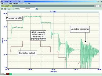
The loop was then subjected to a series of steps in the closing direction. It can be seen that after the first step in this direction, the valve appeared to oscillate on each step. This got increasingly worse the closer the valve got near its seat. It would appear that the positioner was unable to cope with the forces there, and became increasingly unstable, until it did actually go into complete instability when the process demand signal was zero, and it was actually impossible to stop the flow.
Another thing that can be seen in the test (by observing the relative sizes of the steps of process variable and demand) is that the valve is roughly twice oversized. (This is not too serious. However we recommend that this is about the absolute limit of over-sizing to prevent the possible deleterious effects that can be encountered with badly oversized valves). This valve is very bad and is unable to control at low flows.
Figure 2 is a test on another heating gas flow control loop. The first step down is very much larger than any other step. The flow was then reversed and at the step up to a flow of 75%, a huge overshoot followed by damped cycling was observed. The last two steps were very much smaller than any of the previous ones, and the very last was smaller than the previous. Positioner overshoot is now evident in both these steps. The test illustrates that the valve's performance is inconsistent, and one needs a valve with repeatable behaviour to achieve any sort of reasonable control.
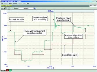
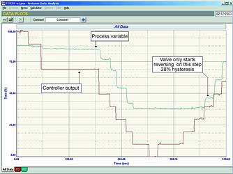
Figure 3 shows a test on an airflow control loop. It can be clearly seen that the valve displays excessive hysteresis (caused by stiction and/or deadband). This measured a vast 28%! The maximum acceptable hysteresis on a control valve is 1%. In addition the valve moved different amounts in a non-repeatable way on most steps, and when the PD was at zero, 40% of the flow was still passing through the valve - really terrible.
A test on another gas heating flow is shown in Figure 4. The valve displays none of the same problems the other valves had, but has very non-linear installed characteristics. This is useless for uniform control action in a cascade secondary loop, which normally has to work over a wide range.
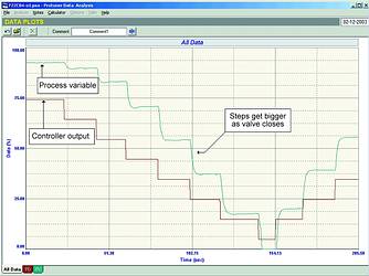
Figure 5 is the gas supply pressure to one of the furnaces. A high frequency oscillation of about 1,5 seconds, with an 11% amplitude can be seen. This was caused by the incoming gas supply pressure regulator being mounted too close to the control valve. There is insufficient capacity in the gas line downstream of the regulator to take up pressure variations, and the regulator is operating in an unstable state. Close coupling of pressure regulators is a fairly common fault found in plants, and it often results in this instability.
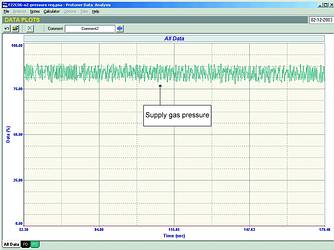
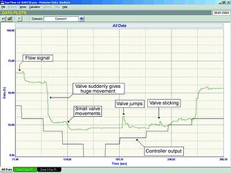
Figure 6 illustrates another problem valve that is completely non-repeatable. Nearly every step is a different, random size. The valve jumps and sticks. When the PD is at zero, the valve is still passing 25% flow. I think it is pretty obvious that one could not expect any form of reasonable control with these valves. Remember a valve's job is to translate the demand of the controller into a flow of a fluid. If it cannot do this, one cannot expect decent control. Even a flow controller operates far too slowly to overcome valve problems in an acceptable time. In the case of slow processes like temperature, a controller can literally take many hours to correct for a valve's problems.
The next article in this Case Histories series, which will be published in two months time, will cover some of the control problems encountered on the second visit to this plant where the loops were optimised after the changeover to the PLC system.
For more information contact Michael Brown, Michael Brown Control Engineering, 011 486 0567, [email protected], www.controlloop.co.za
Michael Brown is a specialist in control loop optimisation, with many years of experience in process control instrumentation. His main activities are consulting, and teaching practical control loop analysis and optimisation. He gives training courses that can be held in clients' plants, where students can have the added benefit of practising on live loops. His work takes him to plants all over South Africa, and also to other countries.
| Email: | [email protected] |
| www: | www.controlloop.co.za |
| Articles: | More information and articles about Michael Brown Control Engineering |


© Technews Publishing (Pty) Ltd | All Rights Reserved
 printer friendly version