

Wi-Fi is now present everywhere and people have become comfortable using it for just about any application. For example, many systems designers are choosing to move their industrial applications from wired Ethernet to wireless utilising Wi-Fi. The advantages of moving to a wireless design are numerous.
Wireless allows for client devices to be located in difficult to reach areas and it saves on installation and wiring costs in remote locations. The benefit of not having to rewire plant infrastructure when relocating machines on the factory floor is yet another advantage. Finally, it is easy to expand as additional devices are required. There are many different Wi-Fi technologies that can be used in industrial applications. Whether it is an existing application or a new design, an engineer must look at the application requirements to make informed decisions regarding which technology to use. When deciding to move from wired to a wireless, the tips presented in this white paper will help ensure that your design is successful.
Tip 1: Know your application’s throughput requirements
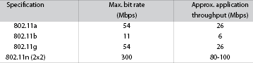
Knowing the data rate at which an application’s client devices will send and receive is critical for planning the network. This information will be used to determine things like which Wi-Fi technology to use and how many access points will be required to provide the desired throughput. In a Wi-Fi system, the actual throughput that is available to an application is generally about 50 to 60% of the overall bandwidth of the Wi-Fi technology selected. This is due to control and management overhead in Wi-Fi systems. If an application needs more than is available, then the application will not work. See Table 1.
Tip 2: Know how many clients will be accessing the Wi-Fi network
This tip goes hand in hand with the application throughput requirement. Wi-Fi works in a similar fashion to how Ethernet hubs work. That is, Wi-Fi uses a single collision zone for all the devices connected to the Wi-Fi network. This means that only one device can transmit at a time, and all the other devices must wait until the network is idle to transmit.
When multiple devices try to transmit at the same time, there is a higher chance that collisions could occur. This causes latency in the network. If you plan to connect many devices to an industrial wireless network, then you should also plan to add multiple access points to allow different clients to use different access points and thereby reduce the number of collisions.
Tip 3: Know how the application will send and receive data
Many industrial protocols send small packets of data that are only a couple of hundred bytes long. Other applications, such as for video or data storage, utilise large blocks of data that require transmitting thousands of bytes. Knowing the characteristics of how your application will use the network allows you to make an informed decision about which Wi-Fi technology is best suited for the intended application. For example, 802.11n is better suited for applications that need to transfer large amounts of data since it contains features that help to optimise large transfers. One such feature supported by 802.11n is called block acknowledge. This feature lowers the amount of overhead in the wireless channel by allowing the receiving device to send an acknowledgement after many transfers by the sender. The result is better bandwidth utilisation. By comparison, 802.11a/b/g sends an acknowledgement after every transfer.
Tip 4: Know which protocols the application plans to use
Industrial protocols and other networked applications use TCP for control applications or when reliability is critical and message loss is not acceptable. This is because TCP allows the receiver to request that missing or corrupted packets be re-sent. TCP is known as a reliable protocol. Contrast this with UDP, which is a connectionless protocol. This means the sender will transmit one packet after another without worrying whether or not the packets were transmitted successfully. On wired networks, typically there is little to no packet loss and the low overhead of UDP can be taken advantage of. However, many other factors need to be considered on wireless networks, such as client roaming or RF interference, which can corrupt packets in transit. While 802.11 has the ability to retry transmissions that it does not receive an acknowledgement for, depending on the length of time the interference lasts, packets can still get lost. What this means is that an application’s sensitivity or tolerance to packet loss must be considered. To mitigate this potential loss, highly available transmission features, such as Moxa’s dual redundant packet solutions, can be employed to avoid this problem. When migrating to a wireless transmission medium for existing applications, application designers may need to tweak the mechanisms used for transmitting data, or make other adjustments.
Tip 5: Determine the capabilities of the client devices that will be deployed on the network
Will the client devices all use the same technology or will there be a mix? Decisions regarding which devices will be supported are critical in maintaining application throughput. For example, if both 802.11b and 802.11g devices need to be supported, there will be less overall throughput on the wireless channel. This is due to the fact that the access point will have to slow down to 802.11b speeds when communicating with those clients. The time it takes to perform transfers at the lower rate steals time from the higher performing clients and limits their overall throughput on the network. If mixed mode operation is required, make sure you have enough throughput to support the application. If you can avoid supporting legacy devices, by all means do so, and limit the access point to only support a particular wireless technology to improve performance. For example, limiting the access point to 802.11g only or 802.11n will improve performance by not allowing legacy devices to connect to the access point.
Tip 6: Plan for throughput
Knowing how much throughput your client application needs is critical when planning how many access points to install. Just because you have selected 802.11n and can support up to 300 Mbps of available bandwidth does not mean that every signal from every access point will transmit at 300 Mbps. The farther a client radio is from the access point the weaker the signal will be, and as the signal gets weaker, it gets closer and closer to the noise floor. The difference between the signal and the noise floor is the signal to noise ratio. A high signal to noise ratio means that a higher performing modulation and coding scheme can be used by the radios. As the signal to noise ratio degrades, the radios must utilise a lower performing modulation and coding scheme to deal with the interference on the channel. This is called dynamic rate switching. This means that the farther the client is from the access point the lower throughput it can achieve. If your application throughput needs are high, then you must design your wireless network with more access points in closer proximity to the client radio’s location, since doing so will ensure that the radio will be able to sustain higher data rates.
Tip 7: Know the application roaming needs.
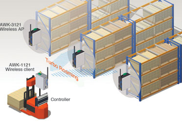
With industrial wireless networks, it is common for clients to move about in a facility. Clients are often used for location tracking or for obtaining the GPS coordinates of an object’s next location. In other cases, the clients are used for machine control on moving conveyors, rail cars, or cranes. The system designer should identify the latency the end application can tolerate while objects move between access points. When a client roams from one access point to another, the time it takes to connect to the new access point introduces a transmission delay. With commonly used Wi-Fi clients such as computers, the delay could be several seconds. If the application requires fast roaming, then plan on using turbo roaming in the design. This means that the client must be a Moxa client radio. Turbo roaming can provide as fast as 100 ms roaming between access points, and if faster roaming is required, then consider a controller based approach such as the Moxa WAC. The wireless controller approach allows for 50 ms roaming for Moxa clients.
Tip 8: Know the characteristics of the environment
Industrial applications are notorious for using machines that can cause RF interference. In addition, industrial applications are often housed in buildings made of metal, or are full of reflective materials. Utilising 802.11a or 802.11n in the 5 GHz band can help to avoid the interference issues of the overloaded 2,4 GHz band. However, as the frequency increases, the range and penetrating power of the signal decreases. This means that you will need more access points or higher gain antennas to obtain the same coverage as in the 2,4 GHz band. It is a good idea to use two antennas per radio in these environments. Two antennas allow the radio to take advantage of the diversity antenna system, which can help manage reflected signals. In addition, 802.11n has the added ability to reconstruct signals from the reflections in these environments using its MIMO capability.
Tip 9: Know how to handle directly connected vs. external antennas
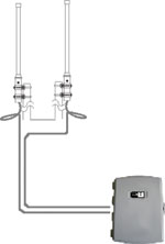
It is common in enterprise or office environments for the access point to utilise built-in antennas or directly connected antennas. These are usually low gain solutions in the 2 to 4 dB range. In industrial environments, it is not uncommon to have the radio mounted inside a control cabinet connected to antennas mounted on the outside or on a pole. In these situations, the engineer must pay close attention to the gain of the antennas and account for all the losses due to the cable and connectors used. In short cable runs, using LMR-200 cable provides for acceptable low signal attenuation. For longer cable runs, make sure to use LMR-400 or above to minimise the losses. For example, a 3 metre LMR-200 cable will have a combined cable/connector loss of 1,9 dB at 2,4 GHz and 2,8 dB at 5 GHz. The same solution using LMR-400 cable has less than half the attenuation. For optimum performance, make sure to minimise and match the lengths of the cables to each remote antenna connected to the radio.
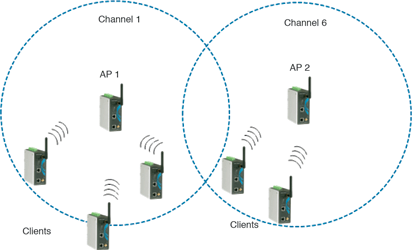
Tip 10: Design your channel allocation plan
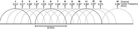
When using more than one access point or when there are other access points in the area, it is important to identify the channels that will be utilised on each adjacent access point. When doing this, it is important to avoid using the same channel as an adjacent access point. In the 2,4 GHz range only three channels do not overlap. These are channels 1, 6, and 11. If at all possible, make sure to stagger the access points in these channels. This will minimise a kind of interference known as co-channel interference. When using the 5 GHz range, each channel is non-overlapping if you’re using a 20 MHz channel width. This is known as HT20 mode. If the access point is using 802.11n with 40 MHz channel bonding (known as HT40), then you need to stagger access points every two channels to avoid overlap.
Tip 11: Pre-plan your access point placement using a predictive site survey
For applications that must utilise multiple access points to provide coverage, it is most helpful to use a software tool to provide a preliminary plan for access point locations. Doing so can result in a big savings later on when visiting the site to perform an actual site survey. These tools typically take in a floor plan of the facility. Using data from the planned access points and clients in use, as well as building materials at the site, the predictive site survey can provide a placement plan for the site as well as the number of access points required to provide the throughput the end application needs.
Tip 12: Perform an on-site survey to identify access point locations
Although predictive site surveys can be useful, they do not take into account the obstacles, machinery, equipment, and other radiating devices inside the building, which is why it is essential to do an on-site survey. Once you have a plan for where you want to deploy the access points, visit the site and perform measurements using the actual radios and antennas that will be used in the deployment. Using the pre-plan as a guide, measure signal levels using the actual devices you plan to use in the deployment to verify coverage. Try to maintain a line of site between the access point and client radios wherever possible. A variety of site survey tools are available on the market for measuring signal levels to create a heat map of the actual coverage in the area and for identifying problem areas. In the absence of advanced site survey tools, plan a 15 to 20% overlap between adjacent AP cells at the minimum data rate required by the application.
Tip 13: Check your work and verify throughput
After the radios are deployed verify the throughput in the network at various locations. Use a software utility such as jperf to measure throughput and verify that adequate throughput exists at edge cases in the Wi-Fi cell boundaries.
| Tel: | +27 11 781 0777 |
| Email: | [email protected] |
| www: | www.rjconnect.co.za |
| Articles: | More information and articles about RJ Connect |


© Technews Publishing (Pty) Ltd | All Rights Reserved
 printer friendly version