

This article continues from Part 1 which was featured in the last issue. We continue to look at the practical operations of noncontact temperature measurement devices and IR thermometry.
Optics and window
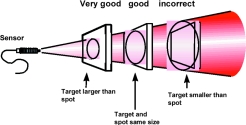
The optical system of an infrared thermometer picks up the infrared energy emitted from a circular measurement spot and focuses it on a detector. The target must completely fill this spot, otherwise the IR thermometer will 'see' other temperature radiation from the background making the measured value inaccurate. (See Figure 7.)
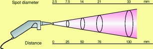
The optical resolution is defined as the relationship between the distance of the measuring device from the target, and the diameter of the spot (D:S). The greater this value, the better the optical resolution of the measuring device, and the smaller the target can be at a given distance. (See Figure 8.)
The optics themselves can be mirror optics or lens optics. Lenses can only be used for particular wavelength ranges due to their material wavelength ranges. They are, however the preferred solution for reasons of design.
For measurement in a closed reaction vessel, furnace, or vacuum chamber, it is usually necessary to measure through a suitable measuring window. When selecting a material for the window, keep in mind that the transmission values of the window are tuned to the spectral sensitivity of the sensor. At high temperatures, the material most often used is quartz glass. At low temperatures (in the range 8,14 µm), it is necessary to use a special IR transmissive material such as germanium, Amtir, or zinc selenide. When choosing the window, consider the spectral sensitivity parameters, diameter of the window, temperature requirements, maximum window pressure difference, and ambient conditions as well as the possibility of keeping the window free from contamination on both sides. It is also important to have transparency in the visible range in order to be able to align the device better with the target (eg, in a vacuum container).
Table 1 gives an overview of various window materials.
The transmittance of the window greatly depends upon its thickness. For a window with a diameter of 25 mm, (which should be able to withstand the pressure difference of one atmosphere), a thickness of 1,7 mm is adequate.
Windows with an anti-reflecting layer exhibit much higher transmittance (up to 5%). If the manufacturer states the transmittance for the corresponding wavelength range, the transmission loss can be corrected along with the emissivity setting. For example, an Amtir window with 68% transmittance is used to measure a target with emissivity of 0,9. Then 0,9 is multiplied by 0,68, resulting in 0,61. This is the emissivity value to be set on the measuring device.
Pyrometers are often fitted with an aligning telescope or with lasers that are either built-in or screwed in front of the device. The laser beam enables the user to aim at the measuring spot even more quickly and precisely, which benefits applications of the IR-measuring device considerably. In particular, it is very useful to sight on the measuring spot with a laser for the measurement of moving objects and in poor light conditions.
One can distinguish between the following laser sighting setups:
1. Laser beam with an offset from the optical axis
This is the simplest model, especially for devices with low optical resolution (for big measuring objects). The laser spot aims approximately at the centre of the measuring object, but there is a noticeable error at close range.
2. Coaxial laser beam
This laser beam comes out of the centre of the optics and remains along the optical axis. The centre of the measuring spot is precisely marked at any measuring distance.
3. Double/twin laser
Twin laser with two aiming points can be used to show the diameter of the measuring spot over a long distance. With this, the user does not need to guess the size of the diameter or calculate it beforehand. Furthermore, it prevents the user from making mistakes during the measurement.
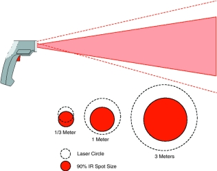
4. Circular laser sighting with offset
This device is the simplest solution to show not only the location of the measuring area but also the size and outer form of it. The measuring surface is within the laser circle from a certain minimum distance onwards. The manufacturer calculates the laser circle to be larger than the real measuring spot in order to reduce the parallax error. Consequently, the user has to ensure that the laser circle as a whole is filled by the subject to have a correct measurement. But this prevents the user from making full use of the geometrical resolution stated for this device (compare red area with laser sighting circle [interrupted line] in Figure 9).
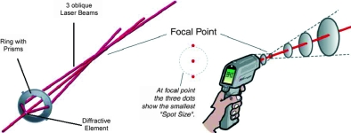
5. Precision 3-point coaxial laser sighting (True Dimension)
A laser beam is divided up to project three bright laser points in a row that enable the user to clearly mark the dimensions of the measurement spot from all distances and measurement angles. The middle laser point always shows the centre of the target, while the two outside laser points mark the diameter of the measurement spot.
In addition, the position of the outer points can be used to indicate the distance to the smallest spot size possible. When the outer points align eg, vertically or horizontally, the distance to the smallest spot size is indicated (See Figure 10).
The use of the laser measuring spot proves to be an effective visual help in guiding the infrared measuring device precisely to the measuring object.
The application of an aligning telescope together with laser sighting is very useful for the determination of the measuring area when optically aimed at bright objects (at high temperatures) or to make measurements in strong daylight or at long distances.
Detectors
The detector forms the core of the IR thermometer. It converts the infrared radiation received into electrical signals, which are then emitted as temperature values by the electronic system. In addition to reducing the cost of IR thermometers, the most recent developments in processor technology have meant increases in system stability, reliability, resolution, and speed.
Infrared detectors fall into two main groups: quantum detectors and thermal detectors.
Quantum detectors (photodiodes) interact directly with the impacting photons, resulting in electron pairs and therefore an electrical signal. Thermal detectors change their temperature depending upon the impacting radiation. The temperature change creates similar to a thermocouple a voltage. Thermal detectors are much slower than quantum detectors due to the self-heating required. (Here, much slower means ms in relation to ns or µs of the latter detectors.) Quantum detectors are always used for imaging systems and line scanners.
Display and interfaces
The interfaces and types of measured value displays available are important to the user. Some devices, especially handheld ones, have a directly accessible display and control panel combination which can be considered the primary output of the measuring device. Analog or digital outputs control the additional displays in the measuring station or can be used for regulating purposes. It is also possible to connect dataloggers, printers, and computers directly.
Industrial Fieldbus systems are becoming ever more significant and afford the user greater flexibility. For example, the user can set the sensors from a control station without having to interrupt the manufacturing process. It is also possible to change parameters when different products are running on the same production line. Without such remote setting options, any change to the sensor parameters emissivity, measuring range, or limit values would have to be made manually at the sensor itself. Since the sensors are often mounted at difficult-to-access points, the intelligent sensor ensures continuous monitoring and control of the process with minimal input from personnel. If a malfunction occurs - ambient temperature too high, interrupted supply, component failure - an error message will appear automatically.
The addressability of pyrometers facilitates operation of a number of devices (usually up to 32) on one network (multidrop operation), resulting in lower installation costs. With the multiplicity of bus protocols and types of fieldbus now available, there are different converters (gateways) on the market which perform the task of converting (translating) device-specific commands into the appropriate protocol (eg Profibus PA). The RS485 is the most-used hardware platform in this respect.
A further advantage of the pyrometer with a digital interface is that it allows field calibration using calibration software available from the device manufacturer.
Special pyrometers
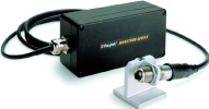
Fibre-optic pyrometers
Pyrometers with fibre-optics are used for applications involving strong electrical or magnetic interference fields. This makes it possible to place the sensitive electronic system outside the danger zone. Typical of these applications are induction heating and induction welding. Since the fibre-optics themselves contain no electronic components, the operating temperature can be raised significantly without the need for cooling. The standard temperature for use is 200°C, with the highest possible temperature up to 300°C. Installation and continuous operating costs per measuring point are low since no water cooling is required.
With modern devices, it is possible to replace the fibre-optic cable and optics without recalibration. Simply input a multidigit factory calibration number. Fibre-optics are available for wavelengths of 1 µm and 1,6 µm. Targets from 250°C can be measured with these (see Figure 11).
Ratio (2 colour) pyrometers
Special pyrometers (also called two-colour or dual wavelength pyrometers) have two optical and electrical measuring channels identical in structure. Both wavelength ranges are placed as close as possible to each other and set very narrow-banded, so that the effect of material-specific peculiarities (reflectance, emissivity) from the target is near-identical to both wavelengths. By means of a mathematical calculation of ratio, certain influences on measurement can be eliminated. The following procedures have proved successful:
1. Splitting the measured radiation using two filters which revolve in front of a radiation detector (filter wheel). Measurement in both channels thus takes place alternately which, in the case of fast-moving targets, can result in errors in ratio calculation (channel 1 sees a different point on the target than channel 2).
2. Splitting of the measured radiation using beam splitters and two radiation detectors fitted with filters.
3. The measured radiation reaches without the beam-splitter a double detector (sandwich design) fitted with filters. Here, the front detector represents the filter for the second detector behind it.
Using the pyrometer equations below for channel 1 with wavelength λ1 and channel 2 with λ2 the result for the measured temperature Tmeas is :
If the emissivity in both channels is the same, then the term after the plus sign becomes zero and the measured temperature corresponds to the target temperature Ttarget. (C2:second radiation constant in µm.K).
The same can be applied to the target surface A, which as A2 and A1 is of course identical in the case of both channels, meaning that here too the term after the plus sign is dispensed with.
Thus, the measurement is independent of the size of the target. Moreover, the object radiation being sent to the pyrometer becomes reduced proportionally, not only when there is a smaller measuring surface, but also when the pyrometer 'gets to see' the target for a shorter time span. By this means, targets that are in the line of sight for a shorter period than the response time of the pyrometer can also be measured.
Changing transmittance characteristics in the measurement path are eliminated in the same way. The devices can be used where there is dust or smoke present, or any other interfering factor that reduces radiation from the target. Modern devices can apply this effect (attenuation) to their own optics, and send out an alarm signal at the appropriate level of contamination (eg, air purge failure with the air-blowing attachment).
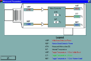
In some applications where the nature of the technology means a certain particle density around the target, a ratio pyrometer with attenuation factor read-out can provide additional information. Figure 12 shows the information given by a ratio pyrometer using PC software. In addition to the temperature calculated from the ratio, the measured temperatures from both individual channels are given. Moreover, attenuation that is calculated by comparing the two is displayed in percent.
Ratio pyrometers can measure temperature when:
1. The target is smaller than the spot or is constantly changing in size (background cooler than target).
2. The target moves through the spot within the response time.
3. The line of sight to the target is restricted (dust or other particles, vapour or smoke).
4. Emissivity changes during measurement.
5. The attenuation factor provides additional information about the technological process or can be used as an alarm in the case of over contamination of lenses or windows.
| Tel: | +27 11 608 1551 |
| Email: | [email protected] |
| www: | www.randci.co.za |
| Articles: | More information and articles about R&C Instrumentation |


© Technews Publishing (Pty) Ltd | All Rights Reserved
 printer friendly version