

Every time I work on a plant that is using a PLC and scada system for feedback control, I always first do a test on a controller module to ensure that the controllers have been configured correctly. I find that they are not working properly in at least 85% of cases! This is because the average person who writes the PLC program has no real understanding of the potential pitfalls.
As mentioned in previous articles, this is because most PLC manufacturers, as opposed to manufacturers of DCS systems, have not provided any safeguards in their system to prevent users from making mistakes. (The DCS people come from a background extending over nearly a century of manufacturing PID controllers from the early analog technology days, and have the experience to ensure that their digital systems provide all the necessary safeguards to prevent users making basic errors).
What are the problems associated with controllers that are configured incorrectly?
1. Controllers not working at all: I have been in at least three plants in my career where system integrators have written controller algorithms and software blocks that have not worked properly, for instance, not being able to change the tuning. Generally, these plants end up running the control loops in manual. Unbelievable but true.
2. Controllers not triggered correctly: controllers should be triggered by an accurate and repeatable timed interrupt, as the I (integral) and D (derivative) terms are time dependent.
3. Controllers triggered correctly, but the wrong scan time entered in the controller’s parameter block: the result is I and D terms that are not calculated correctly. It seems very strange that the scan rate is not automatically set to the same time as the interrupt scan time, but often there doesn’t seem much logical thought used by certain manufacturers. It should be noted that most DCS controllers actually measure the exact scan rate on each and every scan, and the time is incorporated into the control algorithm, so there can be no error.
4. Incorrect control algorithms used by manufacturers: this is very rare these days, but I have encountered a few PLC controllers that do not operate correctly.
5. Incorrect input/output scaling: the calculation performed by the P term in the controller is to take the control error, which is the difference between SP (set-point) and PV (process variable), multiply it by the gain factor, and then send the result to the controller’s output. Now, in the vast majority of cases, the controller’s output is scaled 0-100%. Therefore to be correct, the units of error must also be in percentage.

In modern day digital control systems, people prefer to work in engineering units rather percentages, so it is important that the SP and PV inputs be converted, or that a factor be used to convert the engineering units to percentages. Most, if not all, DCS manufacturers do this for you when you program in your control loop. However, many PLC manufacturers seem completely unaware of the need for this, and leave it up to the user to perform the ‘normalisation’.
As an example: assume the measuring range of a transmitter is 0-200°C, and the system integrator programs 0-200°C as the ranges of both the SP and PV. Now, let’s say the SP is at 100°C, and the PV is at 99°C. The error is 100°C-99°C = 1°C. This is actually a percentage error of 0,5%. However, if the controller manufacturer, or the system integrator, has not compensated for this, the controller ‘thinks’ it is an error of 1%, which it will multiply by the P gain factor.
Assuming that the controllers are actually working (unlike those mentioned in point 1 above), what is the main problem encountered because of incorrect controller operation?
The answer is that if the proportional gain, and/or the integral and possibly derivative terms are not set up correctly, then scientific tuning is not possible as the closed loop responses will be wrong.
This may not worry most people, since very few use scientific tuning methods and surveys show that 98% of all tuning is done by trial and error. However, people who are any good at such tuning have acquired their skill through years of practice. The problem then is that the loops may all behave differently, maybe due to incorrect triggering, or incorrect configuration when using engineering units. Therefore the ‘feel’ for tuning that these people have developed may work differently on each loop, and they find that their tuning skills don’t seem to work anymore.
I always remember a control manager on a large mine saying to me: “I don’t understand it. We have got eight identical plants on this mine, yet the tunings on the loops are completely different for each plant. Surely they should be the same, or very similar?”
The answer was that each plant had its own PLC control system. Even though the PLCs were all the same make and model, each had been programmed by different people, none of whom understood how to configure controllers properly. Therefore, because the PLC manufacturer had not built in sufficient safeguards to prevent configuration errors, the programmers had all done different things. As a result, the controllers all behaved differently, as did the P, I and D terms. Not only that, but the different control loops in each individual PLC operated differently. It was a complete mess.
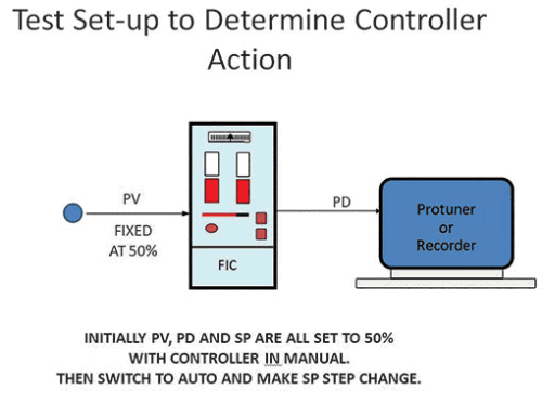
To test a controller for P+I action, one must set up the controller as shown in Figure 1. One needs to use a spare control block, or disconnect the controller in the field. As shown, a fixed 50% signal is fed into the PV input. The PD (output) and SP are then set to 50% with the controller in manual. Then you switch to auto. The PD signal should remain at 50% as the control error is zero. One then makes step changes on the SP and records the PD response.
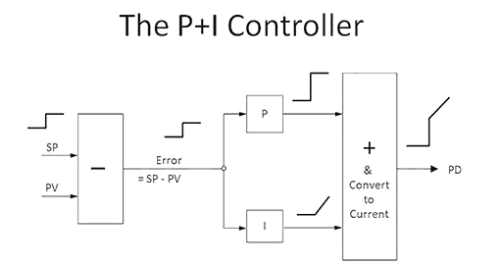
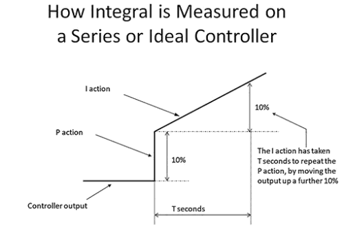
Figure 2 shows a simplified controller and how the P and I terms each react to a constant step change in error. Figure 3 shows how one measures the P and I responses to see if the controller is responding correctly.
Figure 4 is an actual controller test recently performed at a metallurgical processing plant, where they use a very well-known make of PLC. The P in the controller was set to unity, and integral to 2 minutes/repeat. The SP was then stepped by 10%. (The little steps on the recording of the PV during the integral ramp are due to the 1 second scan rate of the OPC system that connected the Protuner to the control system).
On the actual recording it can be seen that the P also stepped up by 10%, so the P gain in the controller was correct. However, the integral ramped up and repeated the P move of 10% in 25 seconds. It should have taken 120 seconds (2 minutes). This means that either the controller block was not being triggered correctly, or else incorrect time settings had been made in the controller setup program.
The implications for the plant are possibly appalling: if all the control blocks have been configured incorrectly, then it will mean retuning every one of over 100 controllers in that plant – a major undertaking. This illustrates how important it is to ensure your controllers are set up correctly.

About Michael Brown
Michael Brown is a specialist in control loop optimisation with many years of experience in process control instrumentation. His main activities are consulting, and teaching practical control loop analysis and optimisation. He gives training courses which can be held in clients’ plants, where students can have the added benefit of practising on live loops. His work takes him to plants all over South Africa and also to other countries. He can be contacted at Michael Brown Control Engineering cc.
| Email: | [email protected] |
| www: | www.controlloop.co.za |
| Articles: | More information and articles about Michael Brown Control Engineering |


© Technews Publishing (Pty) Ltd | All Rights Reserved
 printer friendly version