

Surge level control.
Recently a delegate on one of my courses who works in control on mining mineral processing plants related to me that he was doing some work on a mill sump level control and had found that the input error signal to the controller was the cube of the actual error signal, (SP-PV)3. This resulted in instability and he could not understand why the system designer had done this. I am pretty sure that the reason this had been done was to attempt to provide a form of ‘surge’ level control, but the way it had been done was incorrect. This article will investigate surge level control.
Introduction
Level controls are special cases where one has to be extremely clear as to the purpose of the control. The reason for this is that in the majority of cases of level control, the vessels have relatively long retention times. In other words the volume of the vessel is very large compared with the volume of liquid passing through the control valve, which may be on the input, or on the output of the vessel, as the case may be. This results in relatively tiny process gain. (Refer Loop Signature P1-3, available on CD for persons outside southern Africa.)
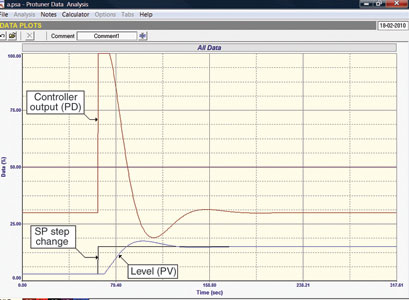
If one is truly wishing to keep the level as constant as possible (tight level control), then it becomes mandatory to use high controller proportional gains, so that the valve moves very quickly in response to changes in load or set-point. It is not uncommon to see gains as high as 10–20 in such cases. This means that if a change in error occurs, one can get very big changes on the output of the controller which in turn results in big changes in the flow through the valve. An example of this is given in Figure 1 where the controller has a gain of 8. A 12% step change in set-point results in a 96% change in the controller output.
Review of the theory
In the previous case history article 110 published in February, it was shown that a controller actually transfers the variance from the one side to the other side of the loop. The higher the proportional gain in the controller the more ‘reactive’ the output of the controller to changes in error on the input of the controller, and the more the valve will move around to correct these changes.
This may be highly undesirable in certain cases, and many of these occur in level control situations. Generally this happens when the actual level is of secondary importance to keeping the control element from changing too quickly in order to keep the flow out of the vessel as constant as possible.
This may sound strange initially. Why put in a level control at all? Why not rather use a flow control? The reason is generally because of two other important and overriding considerations:
The tank should never overflow, for obvious reasons.
The tank should never run empty as that may damage the pump.
A lot of vessels including many sumps used in mining mineral processing are in fact used as ‘buffer’ or storage vessels to ensure that processes downstream can be fed with the liquid from the vessels at a constant rate. In other words, the vessels are there to absorb surges occurring in the upstream processes. The actual level in the tank is not of primary importance as long as the two criteria above are satisfied. The main aim under normal operating conditions is to keep the output flow out of the tank as steady as possible, and if it does change, then the changes should be as slow as possible, so that controls operating downstream can keep up with the changes in flow and do their job in a satisfactory manner.
A practical example
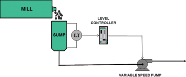
A typical example of this is a mill sump – refer Figure 2. Although one tries to keep the feed into and out of the mill constant, the sump is there to average out any dips or surges on the output feed, so that a really nice constant feed can be supplied to the downstream processes.
To try and achieve the requirements mentioned above, many manufacturers have come up with a variety of relatively fancy controllers. Some of them like notch gain controllers, and error squared on gain controllers are standard blocks in many DCSs. However, as normal, the manufacturers usually give little information on their use and I have found very few people know what they are for, or how to use them. I am typically asked how one tunes such a controller. (Some of the more ignorant manufacturers offer error squared on both gain and integral controllers, which should never be used on level applications, as they will very likely result in instability.)
In my opinion, one should generally not use a controller at all for this application. (The one exception may be in cases where integral is needed to bring the level slowly back to a particular value). In fact, I believe controllers used in this application, in reality create a great deal of confusion amongst plant operating personnel. The reason for this is that you do not actually want to control the level at a particular set-point. So if you do set the controller up properly, the chances are that the process will never be at set-point, and this worries most operators. They generally believe that a controller is only working correctly if the process is on set-point. So what happens in most plants I have been in is that they complain to the instrumentation and control department, and an instrument technician or mechanician goes out and retunes the controller to operate quickly, thus destroying the desired control strategy. (As mentioned in previous articles I have found that the average instrument technician and mechanician do not themselves really understand the process and the control requirements.)
What I would suggest is that the controller be dispensed with entirely, and that the operator be provided with a level indicator only. If it is absolutely essential that he should be able to control the level valve in manual if the need arises, then an auto/manual ‘hand station’ can also be provided.
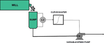
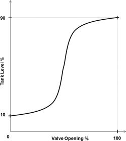
Say we specify that the tank level must never exceed 90% and never drop below 10%. Then to achieve the control requirements one connects the valve to the transmitter via a curve-shaping block (like a polynomial or a ‘look-up’ table). Refer to Figure 3. This sets the valve to a desired position according to the level in the sump.
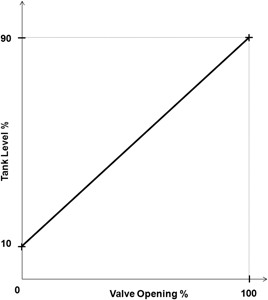
The simplest method of programming the block is by joining the two end points by a straight line. This is shown in Figure 4. Basically it works just like a ball valve that operates between 10% and 90% of the tank level. Thus if the level rises the valve starts opening until it is fully open at 90%, and vice versa for falling level.
This works well, but an even better way of doing it is to design the shape so the valve moves very little at all over most of the level range, and only really moves when the level is approaching the high or low limit. The most effective means of achieving this is to use an ‘error cubed’ curve which is illustrated in Figure 5. Using this method allows very slow and very little movement of the valve over most of the level range, but if the level does reach towards the bottom or top limits, the valve starts moving smoothly, but relatively slowly to prevent the limits being exceeded. (To calculate the graph, one takes the cube of the deviation from 50% level.)
Conclusion
Referring to the question posed by the delegate on the course in the first paragraph, I strongly suspect this was what the control strategy was supposed to achieve. However, for reasons that are outside the scope of this article, it cannot be achieved by cubing the error signal and applying it to a P+I controller, as instability will result. Also as mentioned above, the use of a controller is not a good idea.
Some interesting feedback came from another delegate who was on one of my courses a year ago and was subsequently appointed the senior instrument engineer on a mine in Zambia. The following is taken from an e-mail he sent me recently: “I could not get any stability on the floatation circuits because of all the surges, and the recycles. The biggest upsets were caused by the VSD transfer pumps pumping into the cells. There was great variability in pump speed and the flow/speed non-linearity did not help. I put an error squared algorithm for sump surge control. This worked like a dream. The sump took in the surges and the speed stayed fairly constant. It was very easy to setup, just decrease the gain, until required pump speed variability was reduced enough. This made a quantum difference managing the level in the float cells, from something that would cycle between max and min to a level hovering around set-point.”
This feedback really made my day!

Michael Brown is a specialist in control loop optimisation, with many years of experience in process control instrumentation. His main activities are consulting, and teaching practical control loop analysis and optimisation. He gives training courses which can be held in clients’ plants, where students can have the added benefit of practising on live loops. His work takes him to plants all over South Africa, and also to other countries. He can be contacted at Michael Brown Control Engineering, +27(0)11 486 0567, [email protected], www.controlloop.co.za
| Email: | [email protected] |
| www: | www.controlloop.co.za |
| Articles: | More information and articles about Michael Brown Control Engineering |


© Technews Publishing (Pty) Ltd | All Rights Reserved
 printer friendly version