A petrochemical refinery requested an audit of several critical base layer control loops. This article discusses a problem found with a valve that controls the flow of fuel to a heat exchanger. The actual temperature control of the exchanger was managed by a cascade master temperature controller, which adjusted the set point of the secondary steam flow controller. This control was crucial, as a significant portion of the plant downstream from the exchanger relied heavily on maintaining the correct temperature at all times. Even small deviations from the desired temperature set point could lead to issues. While the operators reported that the temperature control system was functioning well, the engineering supervisor included it in the audit due to its critical importance.
Why does one use a cascade control system?
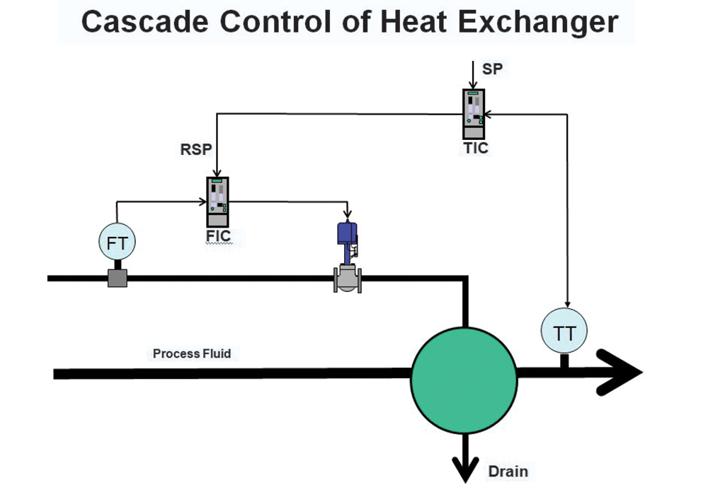
Figure 1 illustrates the schematic of a cascade control system that can be used in a heat exchanger, where the process fluid is heated by steam to reach a desired temperature set point. It may seem unusual to some that the output of the temperature controller (the primary or master controller) does not connect directly to the steam valve. Instead, it is directed to the set point of a flow controller (the secondary or slave controller). This flow controller is the actual device responsible for regulating the flow of steam into the heat exchanger.
There are some very good reasons why this is great strategy:
• As discussed exhaustively in my articles, valves are largely mechanical devices and are ‘the weakest link’ in a control loop. They can suffer from all sorts of problems. Typically 70 to 75% of all control valves are generally suffering from some sort of problem, such as hysteresis, nonlinear installed characteristics, incorrect sizing and stickiness, to name just a few. These have been discussed in detail in many of my articles.
• In a stand-alone control loop the controller output (PD) sends a signal to the positioned/actuator/valve combination, which is effectively instructing it to pass a certain amount of the product passing though it so as to satisfy the control requirements. In reality the signal merely opens the valve to a certain position that is proportional to the value of the PD, and it is by no means certain that the valve was sized and calibrated correctly so that it actually is passing the desired quantity though it. One of the main reasons that the flow control loop is incorporated is to ensure that the correct amount of product does actually pass through the valve. If the correct amount is not achieved then the feedback controller will carry on moving the valve until the PV process variable (PV) does actually reach set point (SP).
• The next reason as to why this is a good strategy is the fact that cascade control is normally used on processes with relatively slow dynamics. Now again as discussed in previous articles a fact of life in feedback control is that whereas processes with fast dynamics can be controller reasonably quickly, slow processes can only be controlled slowly. Instability will result if you try and speed up the control. This means that if the valve does not pass the correct amount of product though it, then the temperature controller can only correct for that as well in a very slow manner. Flow control on the other hand generally has extremely fast dynamics relative to slow procedures like temperature and pH, and that means that the cascade secondary flow controller can quickly get the valve to the correct position. The primary controller, which is there to handle the control of a generally much slower process, would on its own,take much longer to get an imperfect valve to the correct position. Therefore the cascade secondary flow loop gets the valve to the correct position relatively quickly, so the valve problem does not impact adversely on the slower temperature process.
People often ask me how to go about tuning cascade loops. It is very simple, and the procedure is to start with the secondary control loop. One puts the set point of the controller of this loop into Local, so it is not affected by the master controller, and then one performs the normal open and closed loop tests on this loop.
Once these are complete, and if the controller is now tuned correctly, then the set point of the secondary controller is placed back in Remote, which is the signal coming from the PD (output) of the master controller. Then, normal open and closed loop tests are conducted on the master loop, and the tuning is calculated.
I think that what confuses people is that when looking at tuning the primary loop it appears that one has to look at two controllers, two transmitters and only one valve, but in actuality just think of the secondary loop as a complete final control element on the output of the master controller, so when you do the open loop step tests to determine the transfer function of the process, all the elements are included in the PV response to a PD change, and the Maths takes care of all those different elements.
I love tuning cascade loops because I know that the cascade effectively eliminates all the valve problems, and one can rely on the fact that the reaction from the step change of PD accurately represents the process and that it is generally not affected by problems in the final control element.
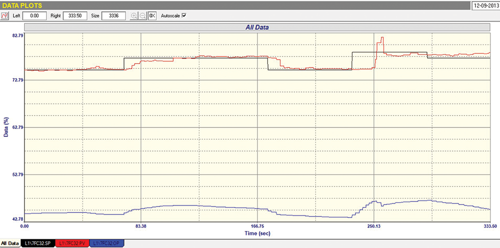
For this case, we will examine the tests conducted on the secondary steam flow control loop in the heat exchanger. Figure 2 illustrates the “As Found” closed-loop test with the tuning settings observed in the controller. The controller was set to local set point, and set point (SP) step changes were implemented.
From the figure, it is evident that during the first upward SP step change, the control response was relatively good, with the process variable (PV) reaching the SP in approximately 40 seconds. However, during the subsequent downward SP step, the flow did not change for about 10 seconds, which suggests that the valve may have been sticking or experiencing hysteresis. Although this behaviour was not too severe, the next upward SP step revealed a different issue. In this instance, the valve took around 17 seconds to respond before it moved, and when it did, the PV overshot significantly. During this delay, the proportional-derivative (PD) controller had ramped up by 4% to prompt movement. Following this, the PD quickly reversed, causing the PV to drop below the SP and remain there while the PD slowly increased again to bring the PV back to the SP. When the SP was stepped down by 1,5%, the PV remained unchanged until the test concluded, with the PD gradually ramping down while trying to position the valve correctly.
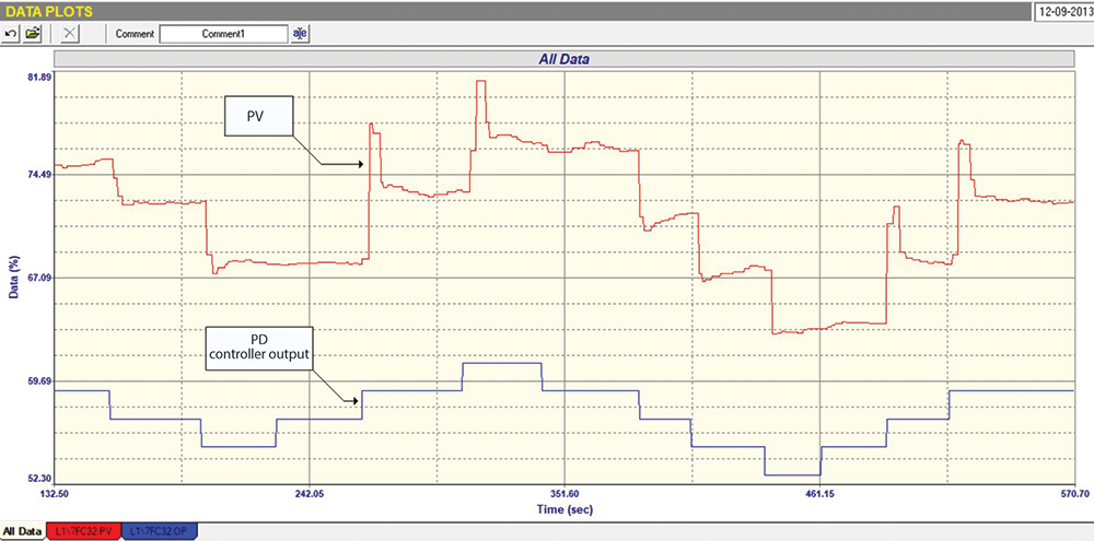
This test shows that there are relatively bad problems with the final control element, consisting of the positioner/valve combination. There is possibly hysteresis or stickiness and an element of instability, as seen with the big valve overshoot. These facts were confirmed by the Open Loop Test, part of which is displayed in Figure 3. It can be seen from this test that:
• The valve is about 2,5 times oversized (Ratio of PV change to PD change). This is not good, as oversized valves, as oversized valves multiply all faults in the valve by the oversized value.
• There is about 2,5% hysteresis on the valve, which is not too good.
• The valve is sticky, as it takes quite some time for the positioner to get it to the correct place after a step.
• There is a massive overshoot on the steps when opening the valve. This is bad.
• When checking the tuning from the steps in the test, it was seen that the original tuning, as found in the controller, was quite satisfactory.
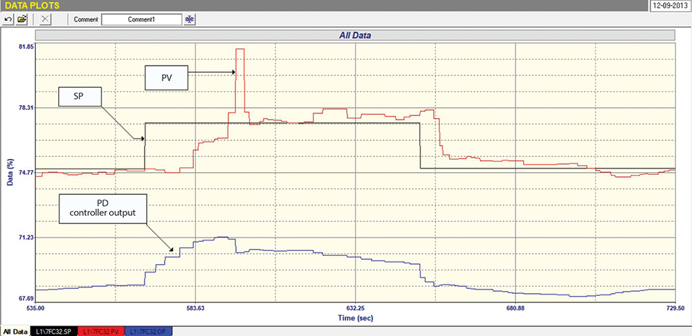
• Figure 4 shows a final Closed Loop test with a slightly faster tune. Here, it can be seen that the control performance was very similar to that seen in the first as-found Closed Loop Test. Noticeable delays occurred when setpoint (SP) adjustments were made, while the proportional-derivative (PD) control action increased to move the valve through its hysteresis and stickiness. This also highlights the challenges faced by the controller in achieving the process variable (PV) to match the setpoint precisely.
However, as mentioned earlier, the temperature control surprisingly performed well despite the valve issues, demonstrating the effectiveness of the cascade strategy. If the temperature controller’s PD had been directly connected to the final control element, it is very unlikely that the temperature would have reached the setpoint.

About Michael Brown
Michael Brown is a retired specialist in control loop optimisation, with over 50 years of experience in process control instrumentation. His main activities were consulting and teaching practical control loop analysis and optimisation. He presented courses and optimised controls in numerous plants in many countries around the world. Michael is continuing to write articles based on the work he has done, and his courses are still available for purchase in .PDF format. He is still handling the sales of the Protuner Loop Optimisation software. He is happy to answer questions people may have on loop problems.
| Email: | [email protected] |
| www: | www.controlloop.co.za |
| Articles: | More information and articles about Michael Brown Control Engineering |


© Technews Publishing (Pty) Ltd | All Rights Reserved
 printer friendly version