

I was recently asked to optimise some loops in a petrochemical plant. Most of the time when doing this sort of work, improvements are the order of the day, and I normally go home at the end of the day feeling pleased with life. However, every once in a while things don't work like that and then I can get very depressed. On this particular occasion, nothing went right.
As a very general statement, when optimising a system, one firstly optimises the fastest and least interactive processes, such as flows and levels, which are normally quick and easy to optimise. Furthermore, as I generally find them badly tuned, clients are usually amazed at how much better they operate when optimised correctly. Only then does the realisation start dawning as to how badly the rest of their plant controls must be working, if the easy ones are so bad.
On this particular day, it was impossible to get any loop tested to work properly. The problem lay with the valves. They all exhibited horrific problems, probably mostly because they were old, and probably also due to bad maintenance.
In previous articles I have stressed how important valves are. In essence the valve is a critical component in the loop and it should faithfully follow the controller's output signal. In particular, you must have a good valve for slow processes. However, on fast processes like flow, one can generally manage to tune the controller in such a way that even if the valve is poor, relatively acceptable flow control can be obtained until it is possible to take the valve out and work on it or replace it, and then really tune the loop well.
On this sad day the valves were too bad to get the loops to work in any way without a cycle, short of completely detuning them. Although people are always very polite and friendly to me, I am sure they must start doubting me when loop after loop starts cycling after being tuned, although I do my very best to explain that it is not the tuning, but is due to poor valves. Therefore, when I left the plant at the end of the day I was not feeling at all happy.
This article will deal with a couple of these loops.
Figure 1 illustrates a closed loop 'as-found' test where setpoint changes are made with the original tuning in the controller. This test is particularly interesting. Apart from illustrating typically very poor tuning, it shows major valve problems. The valve is sticking badly all over the place as it opens. One can see the controller output ramping under the influence of the integral term, until the valve moves, and then it sticks again, and the controller starts ramping again.
The open loop analytical test is shown in Figure 2. It can be seen that the valve is approximately three times oversized as the movement of the process variable is three times more than the movement of the controller output (refer 'Loop Signature' articles for further explanation). Furthermore, the valve exhibits the phenomenon of negative hysteresis, which causes it to overshoot on every reversal. This indicates that the actuator of the valve has insufficient power to overcome the static frictional force that arises every time the valve reverses. The positioner then pumps too much pressure into the actuator to get the valve to start moving. The excess pressure then causes the valve to overshoot when it finally does start moving. Negative hysteresis is very undesirable as it can result in a continuous cycle on fast loops - which perforce need to be tuned with fast integrals.
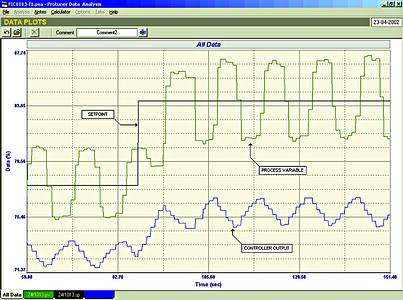
This is exactly what happened on this process. Figure 3 shows the loop in automatic, undergoing a setpoint change. The integral term in the controller is ramping trying to get the valve to move the process to setpoint. However, when the valve moves, the positioner causes the overshoot, and then the whole thing is repeated in the reverse direction, causing a form of instability.
It is also of interest to note that the amplitude of the cycle was over 6%. This would have been only 2% if the valve had been properly sized, as oversized valves increase the amplitude of a cycle as seen on the process variable, directly proportional to the amount of oversizing.
The next example is also very interesting. Figure 4 shows the closed loop 'as-found' test on another flow loop. The response here looks almost identical to that in Figure 1 for the previous example. Again, the tuning was poor with integral far too slow. However, it allows one to immediately see that when a step change of setpoint is made, there is also a very serious problem with this valve as it keeps sticking whilst being moved at a slow ramp rate. When stuck, the controller's integral term ramps until the valve starts moving again. What is noteworthy is that the valves in both of these examples did in fact suffer from different problems.
Figure 5 shows the open loop test with step changes of equal magnitude being made on the controller output in both directions. Step changes 'shock' the valve and are not good for revealing sticking and slipping phenomena. However, the test does illustrate that on the reversals the valve is suffering from excessive normal hysteresis, and is also oversized about 2,5 times. (Remember that oversized valves increase control variance directly proportional to the amount of over sizing, and if cycling occurs the amplitude will be bigger again in proportion to the amount of over sizing.)
The final test with a relatively slow over-damped tuning is shown in Figure 6. This is a wonderful example of a stick-slip cycle. This type of cycle, which looks very similar to the cycle seen in the previous example (Figure 3), is in fact due to different causes. As discussed in previous articles and in particular in the 'Loop Signature' series, stick slip cycles occur on roughly 15% of all fast self-regulating loops. It is caused by a combination of sticking and slipping in the valve and by the fact that on fast processes the integral term in the controller needs to be tuned fast. Therefore, during the stick phase the integral tends to 'wind up' slightly, causing the controller output to move too far.
How does one differentiate between cycles caused by unstable tuning, and those caused by valve problems as illustrated in this article? Firstly, the frequencies of the cycle are different. Typically on flow loops, an ultimate cycle (caused by unstable tuning) has a period around 5 seconds. Cycles caused by instability in a positioner or a combination of a positioner on an undersized actuator have cycle periods of about 20 seconds, whilst stick-slip cycles generally have periods about 40 seconds. Apart from this the waveform shapes are also very different. A cycle caused by unstable tuning exhibits virtually sinusoidal waveforms on both process variable and on the controller output, whilst both the other types of cycle display more of a squarish waveform on the process variable, and a definite saw-tooth shape on the controller output's waveform. In the case of the slip-stick cycle in particular, the saw-tooth changes direction at exactly the same time as the process variable starts reversing (which is as the valve starts moving in the reverse direction).
Problems like these result on poor control variance, and do not make life easy or happier for people like myself who are trying to improve the control in a plant.
For more information: Michael Brown Control Engineering, 011 486 0567, [email protected], www.controlloop.co.za
Michael Brown is a specialist in control loop optimisation, with many years of experience in process control instrumentation. His main activities are consulting, and teaching practical control loop analysis and optimisation. He gives training courses that can be held in clients' plants, where students can have the added benefit of practising on live loops. His work takes him to plants all over South Africa, and also to other countries.
| Email: | [email protected] |
| www: | www.controlloop.co.za |
| Articles: | More information and articles about Michael Brown Control Engineering |


© Technews Publishing (Pty) Ltd | All Rights Reserved
 printer friendly version