Optimisation of regulatory control systems is not easy. It is also time consuming and hard work. There are generally no short cuts. Many people often do not realise this, and are always seeking for a magic tool to take care of problems and do optimisation for them.
Unfortunately in the real world of industrial control where we have to use real valves, and have to deal with the often harsh and complex processes found in our plants, there are no, and never will be, magic devices capable of performing optimisation automatically for us. Yes, there are certainly great aids in the form of computerised devices like digital controllers, smart transmitters, smart valve positioners, loop analysers, and tuning packages, which can make our task considerably easier, but these are all merely tools which must be used correctly.
In general about 85% of loops in nearly all the plants I have been in are operating inefficiently in automatic, and very few people (including the control people) are aware of this. The reason for this is that until recently there has never been any teaching of truly practical regulatory control, and the vast majority of people in the field have no real understanding of this subject. This is because control as taught in educational institutions is highly theoretical. Most people on entering into this field find they cannot generally use what they were taught, and 'learn to fly by the seats of their pants'. Also over the years people have accepted the way loops are operating as normal, as they have no concept at all of how much better the controls could operate if they were optimised properly.
Many practitioners in this field often treat the above comments with great disbelief and derision. I often meet people who have been sent by their companies to attend my courses. Sometimes a delegate will start with a reluctant and even aggressive attitude. However, in the vast majority of cases at the end of the training, this attitude is completely changed, and they are highly enthusiastic, because during the courses they have learnt a new and very practical approach to control which for the first time in their careers has given them a very deep and true understanding of all aspects of what is involved, and what can occur in regulatory control systems. This understanding is the only true magic.
In this month's article, to illustrate the typical lack of understanding and awareness of problems that exist in the average plant, I would like to show a few examples taken from a mining plant where I recently spent some time in helping them optimise their loops.
The control system in the plant was one of the latest, very popular European makes of PLC. As mentioned in my Loop Signature series, which are generally published in alternate months, I normally find that there are more problems where PLCs are used for control as opposed to DCSs. The main reasons for this are that PLCs are often very limited in their analog control capabilities, and also because their programming is too versatile, and not structured enough to prevent people from doing silly things.
This mining plant is a good example. The first thing found was that the PLC programmer for some reason had not used the perfectly good PID block that was supplied as standard by the manufacturer of the PLC, but had written his own. On testing the performance of this block, it was found that it was completely faulty. Firstly, there was no proportional action at all, only integral. Secondly, the integral was not adjustable.
This finding was quite staggering as it meant that not a single control loop on the whole plant could be working properly. The plant is quite a few years old, but to date nobody was aware of this problem, although there was a general 'feeling' that the controls were not too good.
A decision was then made to replace all the PID blocks with the standard block. The system integrators were called in to perform this task. A senior programmer did this work. He had extensive experience on the make of PLC, and had used the PID block many times in the past on other applications. However, on testing the new blocks it was found that the integral was not working correctly. The reason for this is that (like many other PLC programmers) he had not triggered the PID block on a regular and accurate timed interrupt. Programmers assume that because there is a place for entering the scan rate in the control block, the PID is executed at this rate. Most PLCs do not work that way. The scan rate entry in the control block is to merely tell the block at what rate you, the programmer, have set the activation of the block. It is vital for PID control to get this right, as both the integral and the derivative terms are entirely time dependent.
The next thing found was that there was no written description of the system operation. Many programmers had worked on the program over the years, and virtually none of them had left any comments on what they had done. Thus it became a nightmare to try and sort out what was actually happening, and to try and ascertain what the controls should actually do. At the time of writing this, the mine is trying to reach a decision whether they should rewrite the whole PLC program. This is an extremely hard thing to do in a working plant. In the meantime we were asked to optimise as many loops as possible.
Once the PID function was sorted out, the process manager asked us to look at the level control of some tanks. These were a source of major concern as they were always flooding or running empty. People had been trying to sort out the control for a long time without success.
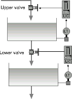
The first thing one should do when performing optimisation, is get a full understanding of the actual process, and then to ascertain what the control is supposed to do, and also find out what problems exist. The sketch shown in Figure 1 was given to us. Essentially there were two tanks one above the other. The top fed into the bottom, and it was desired to control the level in each.
On inspecting the tanks in the actual plant, it was found that the drawing was incorrect in quite a few respects. Several feeds from other sources came into the tanks. There were other outlets with control valves and basically nobody in the plant was really sure how the whole system was supposed to work. Just trying to tune loops blindly is usually a waste of time until one really understands the system operation and what is required of the controls.

Preliminary tests were performed to try and get some semblance of control operating for the meantime. To tune a level loop, the first thing one must do is to get the level to stay constant by balancing the outflow and the inflow. It was found that this was impossible to do. At the time of the test there was virtually no outflow from the tanks, and it was found that the level was rising even though the inlet valves were shutoff. Further investigation showed that the valves were passing at least 30% of the maximum flow when they were in the fully closed position! There is no way that the levels can be controlled with valves like that. People in the plant had been trying to tune these loops for months without having found out that there was a valve problem.
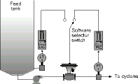
Another interesting example of lack of understanding is the control system shown in Figure 2. Slurry was being fed to the inlet of a cyclone from a tank. Ideally a cyclone operates best if its inlet feed is kept at a certain constant pressure. The problem in this case was that the product feed into the cyclone feed tank was variable and could not be controlled. Therefore, if one is controlling the tank's output flow to keep the cyclone inlet's pressure constant, it is almost certain that the level in the tank will either rise or fall depending on the rate of product feed into the tank, and the tank could either overflow or run empty.

To try and solve this problem, the mine had installed two controllers on the system, one being a level, and the other a pressure controller. The latter was normally in control. However, when the tank level got too close to the top or to the bottom, the level controller took over the control. Pressure and level controllers have perforce extremely different tunings. Therefore, when the other controller took over it caused a huge bump in the system. Even if one were to try and introduce some way of doing it more smoothly, the cyclone inlet pressure would vary a lot - which is most undesirable.
Typically, say the tank level was rising and reached the point where the level controller took over. The valve then opened right up causing the cyclone inlet pressure to rise dramatically. After a while the level would start dropping and soon reached the point where the pressure controller took over again. Once again the valve would shut, and the level in the tank started rising and would soon switch over to level control again. The whole thing was very cyclic.
One of the basic laws of control states that you cannot control more variables than the number of valves available. There is only one valve here. You have to choose if you wish to have level or pressure control. It is impossible to have both. In this case one has to face up to the fact that the level control is the more important, as the tank must not be allowed to run empty or to overflow. The only solution is to use a form of level control that minimises changes in valve position, and to try and keep the cyclone inlet pressure as constant as possible with the slowest possible changes to it.
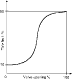
To achieve this one must arrange that the control system will operate so that the valve will be fully open when the level in the tank is near the top, and fully closed when it is near the bottom. Between those two points, one would like to arrange that the valve moves as little as possible. The easiest way is to draw a straight line between the two points, and program a lookup table connected between the output from the level transmitter and the input to the valve, so that the valve moves in a linear fashion between the two extremities in proportion to the level in the tank. However, there is nothing to stop one from shaping the line in such a way that the valve movement is minimal when the tank is mid-level and slowly increasing this as the level starts moving towards the extremities. A typical method is to use an 'error squared' shape, which is based on the square of the difference between the level at 50% and the actual measurement at a particular time. Other curve shapes can be designed as one pleases. A typical curve is shown in Figure 3. It can be seen that there will be very little valve movement whilst the level is in the middle tank region.
If one were to employ this technique on the cyclone it would minimise cyclone pressure inlet pressure variations. It may not keep the pressure at exactly the desired value, but it is the best solution to the problem.

These examples show how 'hit and miss' the control was in the plant. It had been that way for many years. Instrument technicians had come and gone. Most had tried to tune the loops blindly, making no attempt to gain understanding of the processes and controls. As a result no one had succeeded, or even more importantly, picked up the problems as detailed above. Once one gains the 'magic' of understanding what one is trying to do, everything becomes a lot easier.
Michael Brown Control Engineering
011 486 0567
Michael Brown is a specialist in control loop optimisation, with many years of experience in process control instrumentation. His main activities are consulting, and teaching practical control loop analysis and optimisation. He gives training courses that can be held in clients' plants, where students can have the added benefit of practising on live loops. His work takes him to plants all over South Africa, and also to other countries.
| Email: | [email protected] |
| www: | www.controlloop.co.za |
| Articles: | More information and articles about Michael Brown Control Engineering |

© Technews Publishing (Pty) Ltd | All Rights Reserved