

I was asked recently to sort out some control problems in a chemical plant. One of the problems of concern was an important process where it was desired to control the flow of a liquid, split into four streams, which were passing through a furnace for heating. It was desired to keep the flows as constant as possible, and if they did change, then the changes should be kept as slow as possible. The reason for this will be explained later.
System description
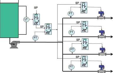
The system is shown in Figure 1. The liquid is pumped out of a tank; the level in this is not important, except that it must not go too high or too low that it causes overflow of the tank or cavitation of the pump. To achieve this a level controller is employed and cascaded to a flow controller, which in turn is cascaded to the four parallel controllers in the individual streams.
If the flows through the furnace change then the furnace temperature is affected; it is vital that this temperature be kept at as close to set-point as possible. The process specifications actually call for the temperature to be kept constant within a 1°C range, which is extremely difficult to achieve. The problem is that the temperature is a slow process and as discussed in previous articles, slow processes can only be controlled slowly. Therefore, if the liquid flows changed quickly the temperature control would not be able to catch the resultant temperature swing.
Control philosophy
When the control system was being implemented, the system designer had correctly recognised that the level control could be very slow as long as the high and low limits were not exceeded, so he had implemented a non-linear level control system using a controller employing an error squared algorithm.
This algorithm is usually included as a standard option in most DCS control systems. (It is very seldom offered as standard on PLCs and usually has to be specially programmed.) It works by squaring the error as the PV moves away from set-point, so in cases like this, the set-point is usually set at 50% and the control action is extremely slow with small errors but increases in a ‘squared’ manner as the error increases. This is supposed to result in very little control action near the 50% set-point level, and the response gets faster and faster as the level moves further away from set-point.
Problems with the strategy
Unfortunately the system did not work as planned. The operators would get the processes operating at desired value and when the plant was running at steady state they put the controllers into automatic. All was well as long as the steady state conditions lasted, which in this type of plant could be for months, but as soon as a load disturbance occurred on any of the processes in the system, the level and associated flow controls started a slow cycle that could go on indefinitely. The operators had to intervene, and take over the controls in manual.
There are two reasons why instability could occur. The first is due to the double cascade system. A double cascade system was fully discussed in Case History 126, entitled ‘Crazy Control Strategies’ which was published in July 2012. The system was very similar in fact to the one discussed here, which is not surprising as they were both in the same plant.
The article explained how essential it is that a cascade secondary process must be very much faster than the primary process, or interaction can occur and cycling may well result. The single flow controller cascaded from the output of the level may therefore cause interaction with the four flow loops cascaded from its output. This flow controller is in fact completely superfluous, and should be removed. The output from the level controller can then be fed directly in parallel to the set-points of the four flow controllers.
The second reason for instability is more complex. The error squared level control could also cause cycling to occur if applied incorrectly.
Level control is a subject that has been discussed in great detail in previous articles. Control of level can be implemented in one of two ways depending on the process requirements:
1. The more common requirement is to keep level constant under changing load conditions or occasionally to follow set-point changes. This requires a fast response, and the tuning must generally be as fast as possible particularly if the vessel has a long retention time. Therefore one usually puts relatively high proportional gains into the controllers, which can cause rapid valve movements when changes occur, particularly if they are step changes in set-point. This results in rapid and possibly large changes in the flow through the valve, and one must always bear in mind this can affect downstream processes. This type of control would be completely unacceptable in the current case.
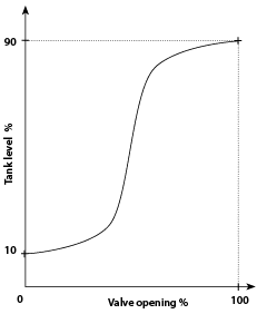
2. The second type of level control is where the level is in itself relatively unimportant, and as in this case, the only reason that level control is being employed, is to prevent it going too low or too high. A completely different control philosophy needs to be applied here. It is usually referred to as surge level control. In my article Loop Signature LS1-29, it was suggested that for several reasons normal types of controller should not be used, and it was far better to merely insert a simple ‘curve shaping block’ between the transmitter and the valve to control the valve in such a manner that very little and slow movements of the valve occur over most of the tank range, but that the valve will start moving faster but smoothly near the high and low limits. A typical curve that could be inserted in the block is shown in Figure 2.
What is wrong with the use of the error squared controller that had been implemented? The problem with such a controller is that people do not know how to apply them properly. When using this form of control on integrating processes, such as levels, the control will work if the squared error is only applied to the P term and integral is not used. If it is applied to both the P & I terms then instability can easily result. The reasons behind this are complex and are beyond the scope of this article.

Michael Brown is a specialist in control loop optimisation with many years of experience in process control instrumentation. His main activities are consulting, and teaching practical control loop analysis and optimisation. He gives training courses which can be held in clients’ plants, where students can have the added benefit of practising on live loops. His work takes him to plants all over South Africa and also to other countries. He can be contacted at Michael Brown Control Engineering cc, +27(0)11 486 0567, [email protected], www.controlloop.co.za
| Email: | [email protected] |
| www: | www.controlloop.co.za |
| Articles: | More information and articles about Michael Brown Control Engineering |


© Technews Publishing (Pty) Ltd | All Rights Reserved
 printer friendly version