

I was recently asked to assist in stabilising the controls on a vessel in a petro-chemical refinery that was unstable, and causing frequent trips and lots of downtime. The process was relatively complex with a variety of fluid inflows into the vessel, some of which had to be in ratio to the main feed which consisted of a very sticky viscous product. In addition steam was also injected into the vessel to control temperature. The difficulties being experienced were also amplified by the fact that the vessel was hydraulically full, which resulted in interaction between many of the control loops.
Figure 1 is a recording of various critical loops cycling away in a test performed when initially inspecting operation of the controls on a unit. It is quite an eye opener. I do not think that I have ever previously come across so many loops all apparently completely unstable cycling away at a grand old rate. As a matter of interest, the cycling being observed was in fact due to an unstable temperature control loop where the temperature of the vessel was controlled by injecting medium pressure steam into the vessel.
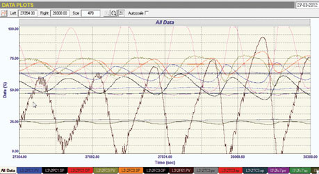
This loop was tuned very badly and was completely unstable. The varying steam coming into the vessel caused a cyclic pressure variation with which all the flows and column pressure controls interacted. Eventually the cycle caused a trip and the unit was down for a long time, at huge financial cost.
It would fill several of these articles describing the various problems encountered whilst getting all the control problems sorted out so the unit ran properly with optimised controls, but this article will deal with two control strategies that had been used on the system which to say the least were crazy. A very interesting valve will also be discussed.
Crazy ratio control system
Very often it is desired to control one flow in a ratio to another. This is often done incorrectly. (Figure 2 shows an incorrect control strategy.) The two flows are measured and the one is divided by the other to get the actual ratio of flows. This is used as the PV (process variable) input to the controller; the SP (set-point) is the desired ratio. The output of the controller goes to the valve of the controlled flow. It looks quite good and very logical.
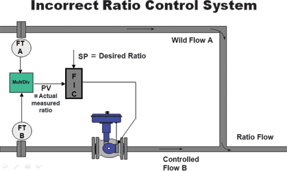
However, the problem is that it can cause instability as one should never use a multiplier or divider in a feedback control loop as it causes change in the process gain (refer Loop Signature P1-3 on my CD ‘Basic Trouble Shooting and Loop Tuning’), this can adversely affect the tuning.
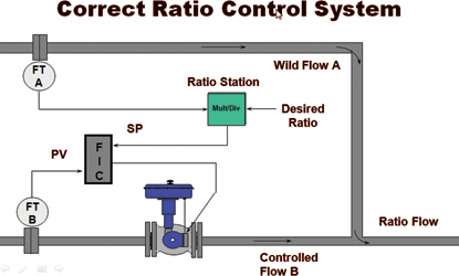
The correct ratio control strategy is shown in Figure 3, which I think is self explanatory. The ratio station which is a multiplier or divider depending on the ratio is now before the set-point and outside the actual loop.
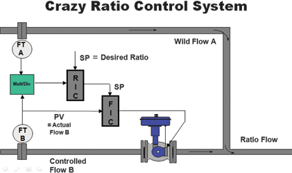
In the unit in question it was desired to control two flows into the vessel in ratios to another flow which was the main product feed into the vessel. The control strategy used is shown in Figure 4. Someone had a distorted idea of ratio control. Firstly, the incorrect control strategy shown in Figure 2 was employed, then, instead of sending the output of the flow controller directly to the valve, it was sent as a set-point to the flow controller which operated the valve. For some reason this was thought to be a good form of cascade control. Now as mentioned in previous articles, I am a great proponent of cascade control, but it only works well when the secondary loop is very much faster than the primary loop. If they operate at the same speed, then it should not be used at all as the loops are very interactive and will cycle – exactly what was happening here. The two controllers were both trying to control a flow and fought each other bitterly, giving ratios which were jumping around all over the place.
We had to prevail on the plant managers to allow us to change the control strategy to the correct ratio control system. This usually involves application to various committees including risk and impact assessments, which can take weeks. In this case the plant had lost so much money through downtime that a quick meeting of senior managers was held and permission was given to change the strategy. The correct system worked beautifully as could be expected.
Crazy level control cascade system
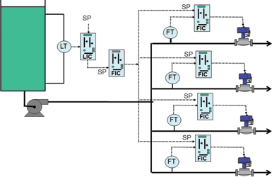
The outlet from the vessel discussed above was fed into another tank. The level in this was controlled by the system shown in Figure 5. The output from the tank is fed into four parallel streams which go to other units in the plant. The flows will change in accordance with the dictates of the level controller which was tuned for ‘tight’ level control i.e. the level was to be kept at the desired set-point as closely as possible. (An advanced control system was also configured to keep the flows in the four streams as equal as possible. This is not shown in the figure as it is not really relevant to this discussion.)
The control strategy as implemented in the plant incorporated a master flow controller the set-point of which came from the output of the level controller. The output of this flow controller was then fed to the set-point of each of the individual flow controllers which individually control the flow of each of the four streams.
Once again someone had come up with a complex cascade system. The level cascades to a ‘master’ flow controller which cascades in parallel to the four individual flow controllers. This is crazy. Firstly, there is no point whatsoever in complicating things putting in the ‘master’ flow controller as it would have made much more sense to send the output of the level controller directly in parallel to each of the four individual flow controllers. Secondly, as discussed earlier, the primary and secondary flow loops all operate at the same speed, so unless one drastically detunes the secondary flow controllers there will be terrible interaction and almost definite cycling.
The net result of the strategy leads to poor level control, because one does want the secondary flow control loops to act quickly so they will not interact with the level loop which is of course slower.
The plant is currently reprogramming the control system to eliminate the unnecessary flow controller.
Bad valve causing problems
Another interesting dilemma encountered with the problems in the unstable controls on the unit, was a valve that was behaving in a most peculiar fashion. It was a large valve with a smart positioner, (which I suspect had not been tuned properly). The valve was controlling pressure in the unit.
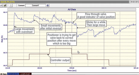
Figure 6 is a test done showing flow and the valve reacting to steps on the controller output. Fortunately there was a flow transmitter in series with the valve, or it is unlikely that we would have ever been able to analyse this problem, as flow through the valve is always the best indicator of valve position.
It can be seen that on a step change when reversing the direction of the valve, it stuck for a while and then drastically overshot. The positioner then tried to bring the valve back to the correct position, but this was at a terribly slow rate. If another step was made in the same direction the valve jumped but never opened any further than the first step. Basically this resulted in very poor control of pressure, and caused a slow type of stick-slip cycle on the pressure.
Much more serious than this was the fact that because the vessel was hydraulically full, every time the pressure controller moved the valve in the cycle it caused interaction on at least three other flow loops feeding products into and out of the vessel, so it looked like they were also cycling.
The pressure control is so important to the operation of the unit that it was impossible to bypass the valve to allow work on it; the problem will have to wait until the next plant shutdown.

Michael Brown’s next practical control course series starts on 17 August in Johannesburg.
Michael Brown is a specialist in control loop optimisation, with many years of experience in process control instrumentation. His main activities are consulting, and teaching practical control loop analysis and optimisation. He gives training courses which can be held in clients’ plants, where students can have the added benefit of practising on live loops. His work takes him to plants all over South Africa, and also to other countries. He can be contacted at Michael Brown Control Engineering cc, +27(0)11 486 0567, [email protected], www.controlloop.co.za
| Email: | [email protected] |
| www: | www.controlloop.co.za |
| Articles: | More information and articles about Michael Brown Control Engineering |


© Technews Publishing (Pty) Ltd | All Rights Reserved
 printer friendly version