It is important that reboiler temperature controls operate well in petrochemical refineries, or the product quality can really suffer. I was asked to check such a control in a refinery where they were having problems with one of these controls. The plant had used a good tuning packet to tune the controls. However, as I have often mentioned, tuning is the last thing that should be done when optimising controls. It is very important to first investigate all aspects of the control loop, including loop components and the control strategy. They had not done this.
The controls in question consisted of a cascade control system with the primary controller being the temperature control, and the secondary one being the cascaded steam flow controller.When analysing cascade control systems, you must always start with the secondary control, which ensures that the final control element performs its function as quickly and accurately as possible. In this particular case, the temperature could respond to changes very quickly, and this made the testing quite difficult as varying temperature could affect the final product adversely, and we had to try and keep the changes we needed to make for the tests as small as possible.
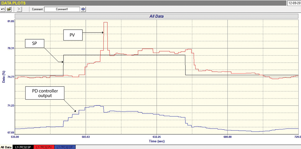
We started with a closed loop test or ‘as found’ on this flow. This is a test where you keep all the existing control settings as they were, and make set point (SP) step changes in automatic. A section of the recording of this test is shown in Figure 1. This is extremely interesting. It can be seen that as the SP was stepped up by some 2%, the flow did not move for almost 15 seconds, but the PD (controller’s output) started moving immediately when the SP changed, and had moved up 2% by the time the PV started moving. This would indicate excessive stickiness or hysteresis in the valve. The flow moved up towards SP and just before it got there, it suddenly shot up way past SP, giving an overshoot of around 150%. The controller immediately reacted and reversed the PD by about 1%. The flow then came quickly back down to SP and stayed there for about 30 seconds, then went up again by just under a percent. It then stuck there whilst the integral action in the controller slowly ramped the PD down, trying to get the flow to move back down, confirming the diagnosis of hysteresis.
On the SP change down, the response again had a delay, but the valve didn’t overshoot on the way down. For a longish period where the SP was constant, it can be seen that it was not possible to keep the PV at SP with the PD ramping up and down trying to get the flow to the right place. A second SP step up and down pretty much mirrored what was seen in the first steps (not shown in the figure).
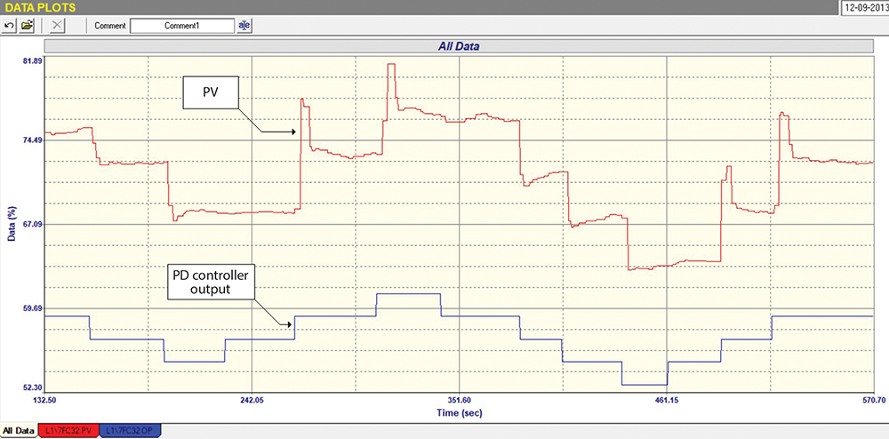
Figure 2 shows part of the open loop test where the controller is in manual and equal steps of PD are made in both directions. We always recommend that there should be a minimum of two steps in one direction, then at least three in the reverse direction, and then a minimum of one back in the first direction again. One should never only make a single step when performing this test on self-regulating processes as this may hide problems.
This test shows some interesting facts:
• The valve is about 2,5 times oversized- which is seen by the ratio of the size of PV steps to those of the PD steps. (See previous articles as to how this works).
• Huge spiked overshoots are again seen on steps when the valve is opening. The positioner at times seemed to be quite slow in getting the valve back to the right position, which could also indicate stickiness in the valve at some places.
• 2% hysteresis is present in the valve.
The main conclusions seen from these tests is that the positioner was not doing a good job and possibly should be repaired or replaced. The 2,5% valve oversize made the problems 2,5 times worse. The tuning done from the open loop test showed that the ‘as found’ tuning parameters used in the closed loop test were pretty spot on, designed to give a nice, fast and stable response.
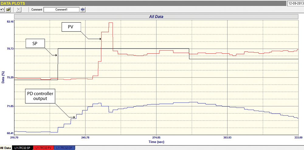
A further closed loop test was done with parameters that should have given slightly slower and a more stable response, with part of this test shown in Figure 3. The Integral term in this test was made faster by about 30% in an effort to get the valve to respond quicker on reversals. However, once again it can be seen that the control is badly affected by the hysteresis and overshoots, making it difficult for the valve to be positioned in the right place to get the PV to SP.
This is another good example of valve problems preventing good control, even when the tuning is good.

About Michael Brown
Michael Brown is a specialist in control loop optimisation, with many years of experience in process control instrumentation. His main activities are consulting and teaching practical control loop analysis and optimisation. He now presents courses and performs optimisation over the internet. His work has taken him to plants all over South Africa and also to other countries. He can be contacted at: Michael Brown Control Engineering CC,
| Email: | [email protected] |
| www: | www.controlloop.co.za |
| Articles: | More information and articles about Michael Brown Control Engineering |


© Technews Publishing (Pty) Ltd | All Rights Reserved
 printer friendly version