

I was recently performing some optimisation at a large chemical plant and was reminded that during the daily hustle and bustle and general high pressure of an instrument and control practitioner, one can easily forget some of the basics. When a problem arises in a loop, many people try and solve it quickly by adjusting the controller tuning, which of course is the very last thing that should be done. You need always to analyse the loop first, and many of my previous articles have dealt with this.
Remember the basics
I have found on quite a few occasions that the last thing that many people look at is the measurement, even though the first law of control states: ‘You cannot control what you do not measure’. On one memorable occasion (which I described in an earlier Case History article) an instrument technician tried tuning a controller for over 6 hours, only to find later on that the problem was actually blocked impulse lines between the orifice plate and the transmitter.
Case study 1
The first example here is a similar type of thing where a measurement technique was being incorrectly employed. A flow was being measured using an ordinary concentric orifice plate and dp (differential pressure) cell. The control was not working well and operators were running the loop in manual.
Figure 1 shows an open loop test that was performed. At first glance it would appear that there is a valve problem, as the controller output is initially being stepped around quite a bit, but with no corresponding changes in flow. However, the people working on this loop had completely forgotten the basics of orifice plate measurement.
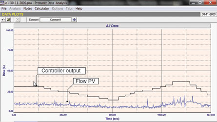
This method of flow measurement is one of the oldest and best established, having been around since the 18th century. Essentially there is a well known relationship between the flow through an orifice and the differential pressure across it. This method of flow measurement is not very accurate, typically quoted by a British Standard as ±2% of full scale over a rangeability (maximum to minimum flow) of 3:1. Over the decades most control people accept that an orifice measurement can in fact be used with good repeatability over a 4:1 rangeability, even though the accuracy will be very bad at the 25% lower end of the scale. However the readings below must be assumed to be absolutely meaningless and should never be used or relied on.
In this case the plant was trying to control the flow at less than 10% of the measuring range. This was impossible with the current measurement setup and there was no more point in doing more work on the loop until the measurement problem was sorted out.
Case study 2
Another example of a measurement problem in the same plant was on a steam flow where it was important to keep exactly on setpoint. However, the flow seemed to be oscillating wildly at maximum range and could not be reduced. This is shown in the open loop test seen in Figure 2, where the output of the controller is being stepped down with no corresponding reduction in steam flow.
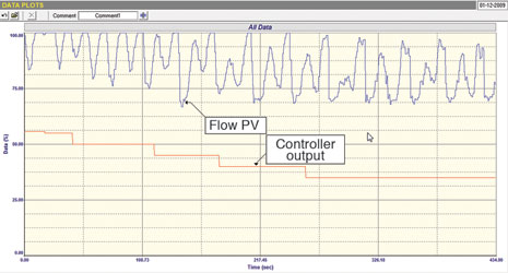
On inspecting the plant it was found that the orifice plate installation was faulty with no condensate pots installed, and 2 phase flow was probably passing through the orifice.
Case study 3
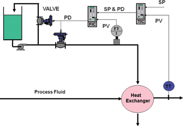
The third and last example is a case of a very poor control strategy employed on a heat exchanger. Figure 3 shows the setup. It is a pretty standard temperature to flow cascade control system often employed on heat exchangers, but with an exception. The valve was not in series with the pump, but was bypassing the fluid used to adjust the temperature from the pump’s output back into the vessel. This was probably to prevent too small a flow through the pump, which may have damaged it.
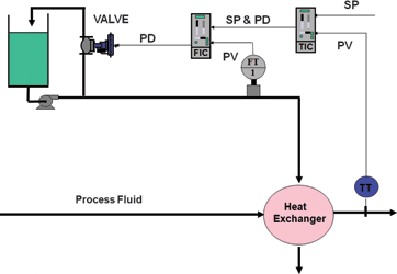
The operators were complaining that the control was useless as it was impossible to bring the temperature of the process fluid to setpoint. In most plants when controls are not working, everyone assumes that the controller tuning is wrong. So, as usual, quite a few people had tried to retune the controllers, but with no improvement.
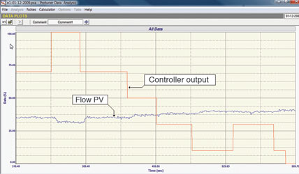
Figure 4 shows the open loop test done on the flow loop. It can immediately be seen that stroking the valve between 0 and 100% only resulted in the flow changing between a minimum of 32% and a maximum of 40%, a measly range of 8%. Obviously the differential pressure across the valve, even when fully open, is much less than the pressure drop downstream of the pump across the heat exchanger. If this was the reason that the bypass valve system was employed, then the best solution would be to incorporate another valve in series with the heat exchanger, and to use split range control. This would ensure that the flow to the heat exchanger could be modulated fully over the whole 0-100% range, whilst still ensuring that the pump always has sufficient flow through it to prevent damage. The revised strategy is shown in Figure 5.
If one did not use identically sized valves, then special precautions would have to be taken to ensure that the process gain remains constant across the whole range. If not adaptive tuning could be employed. This has been discussed in other articles.
In conclusion
The examples given in this article show once again how important it is to analyse fully all components of a control loop and to understand the control requirements before trying to tune the controller.

Michael Brown is a specialist in control loop optimisation, with many years of experience in process control instrumentation. His main activities are consulting, and teaching practical control loop analysis and optimisation. He gives training courses which can be held in clients’ plants, where students can have the added benefit of practising on live loops. His work takes him to plants all over South Africa, and also to other countries. He can be contacted at Michael Brown Control Engineering, +27(0)11 486 0567, [email protected], www.controlloop.co.za
| Email: | [email protected] |
| www: | www.controlloop.co.za |
| Articles: | More information and articles about Michael Brown Control Engineering |


© Technews Publishing (Pty) Ltd | All Rights Reserved
 printer friendly version