


In the previous article in this series, the Bode open loop frequency plot was discussed, and it was shown how certain information pertaining to the dynamics of the process could be determined from it. The focus now turns to what happens when a controller is switched into automatic.
When a controller is switched into automatic, the process and the controller are mathematically multiplied together. By correct tuning, the aim is to produce a resultant known as pole cancellation, which mathematically is a perfect deadtime integrator. This is given by the formula:
C(s) × P(s) = Ke-DTs/s
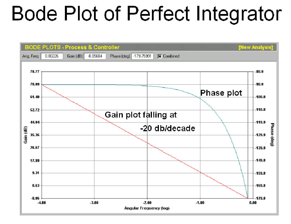
This is, incidentally, the same formula as that for a simple integrating process such as a level control, discussed several times in the first Loop Signature series. The Bode plot of such a process is shown in Figure 1. Note that the gain plot is now a perfectly straight line falling off at a constant −20 dB/decade, while the phase plot, although similar in shape to the Bode open loop plot from the previous article, starts at low frequencies at a −90° phase angle. This is the closed loop, or combined, frequency plot of a perfectly tuned self-regulating process. It is also exactly the same as the open loop plot of a simple integrating process, which will later explain why integrating loops behave so differently from self-regulating loops, mainly because they start out −90° out of phase.
This type of perfect tuning is known as pole-cancellation tuning. There are various reasons why it is the ideal type of tuning, most of which are beyond the scope of this article, but one of the main reasons is that the tuning obtained gives lower controller gain with faster integral which results in less error amplification through the controller and faster recovery from load upsets.
Effect of P, I and D terms on the Bode plot
The controller has three terms: P (proportional), I (integral) and D (derivative) which can alter the open loop plot when they are multiplied with it.
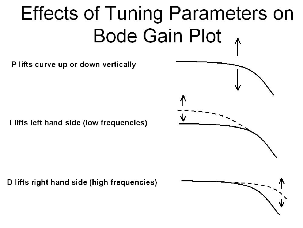
Figure 2 illustrates their effect as follows: The P term has no effect whatsoever on the shape of the plot but moves its position relative to the vertical gain axis. The I term has more effect on the lower-frequency side of the plot and tends to lift up the left-hand side. The D term has more effect on the higher-frequency side of the plot and tends to lift up the right-hand side, but as will be seen later it can have some other effects.
For the simple self-regulating process with a gain, a single lag and a deadtime discussed in the previous Loop Signature article, the open loop plot finishes at the highest frequency at −20 dB/decade. Using the D term would disturb the slope at that end, which is undesirable. The D term should be used only on two particular types of process dynamics, which will be covered later in this series.
For this process, the only term that can be used to straighten the open loop plot is the I term. To tune this controller properly, the I term must first be set to a value that straightens the plot completely, and the P term is then applied to raise or lower the plot to give the desired response. (A later article will show how the values of these terms are determined.)
What happens with imperfect tuning
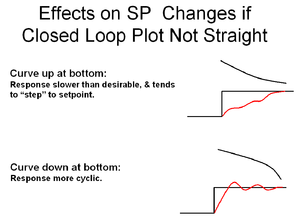
In many situations, whether from incorrect tuning or from process dynamics that cannot be fully corrected, ideal control is not achieved. Figure 3 illustrates the responses to setpoint changes in automatic when the plot is not fully straightened. If the plot is bent upward at the lower-frequency end, the response will be slower than desired, and the process will tend to step upward to setpoint. If the plot is bent upward at the right, the response will tend to be more cyclic than desirable around setpoint.
The rules of instability
A key part of understanding how feedback control loops operate in automatic is knowing when they can become unstable. For continuous cycling to occur, two conditions must be met simultaneously: The combined loop gain must be ≥1 (0 dB), and the phase angle Φ must equal −180°. Unless both conditions are met at the same time, the loop cannot go unstable. If the conditions are close but not met, the loop may cycle for a period with steadily decreasing amplitude.
The ultimate gain and ultimate frequency
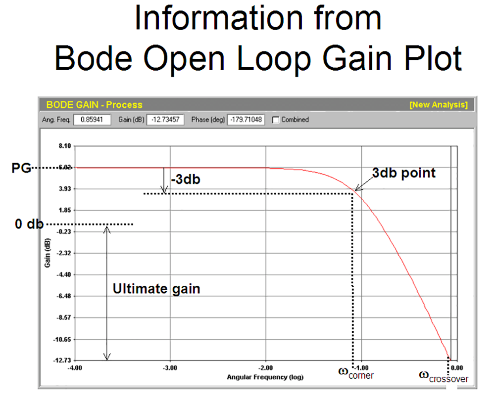
With an understanding of the rules of instability, the ultimate cycle can be defined. The ultimate gain is that gain which, when added to the open loop gain, produces a gain of 1 (0 dB) at the −180° phase point on the Bode open loop plot. This occurs at the crossover frequency, also known as the ultimate frequency. The ultimate period is then 2π divided by the ultimate frequency.
The ultimate frequency is the same as the crossover frequency, so the ultimate period can be calculated from the Bode open loop plot established in the previous article. The ultimate gain can also be measured from the plot as shown in Figure 4. The P term does not change the shape of the plot, but moves it up or down on the vertical axis. If the loop were put into automatic with a P-only controller, the gain would need to be raised sufficiently to move the point at the crossover frequency up to unity gain. Referring to Figure 4, the controller would require a gain of 12,73 dB which equates to an absolute gain of 4,33.
In the next Loop Signature article, the approach to tuning with sufficient robustness and how this is measured in the Bode closed loop plot will be covered.
About Michael Brown.

Michael Brown is a retired expert in control loop optimisation, possessing over five decades of experience in process control instrumentation. His primary focus has been consulting and delivering instruction on practical control loop analysis and optimisation. He has conducted training and optimised control systems at numerous facilities internationally. Mr. Brown continues to author articles reflecting his extensive work, and his courses remain accessible for purchase in PDF format. Additionally, he manages the distribution of Protuner Loop Optimisation software and welcomes inquiries regarding loop-related issues.
Contact details: Michael Brown Control Engineering CC,






© Technews Publishing (Pty) Ltd | All Rights Reserved
 printer friendly version