

Pressure has a major effect on the separation and cut in a distillation column, and column stability can be dramatically hampered if there is poor pressure control. One of the most common ways of controlling the pressure in a distillation column is manipulating the hot vapour bypass around the condenser. In the case of the debutaniser discussed in this article, it was noted that the variability in the pressure increased dramatically in winter. In addition, there was a noted worsening of control during the night. The possibility of optimising this control loop was investigated, and the findings are captured in this article.
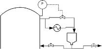
Figure 1 shows the pressure control system that was in place in this column. By increasing the bypass around the condenser, less vapour is condensed and removed out of the closed system, increasing the vapour and pressure in the entire system.
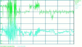
The problem
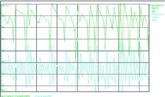
Figure 2 shows the pressure during the evening hours. The pressure can be seen to vary between 820 and 900 kPa within a period of approximately 10 to 15 minutes. The negative effect this has on the product flow (and consequently the accuracy of the cut) can also be seen in the figure.
Unfortunately, no data of open loop testing of the loop is available. However, Figure 3 shows the response of the loop to two setpoint changes. In this figure the blue line represents the valve output (%), while the process variable (pressure in kPa) is the red line. An imaginative setpoint was drawn-in in red dotted lines.
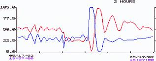
Before analysing the responses to each of the setpoint changes, note that the pressure loop is an integrating loop. The valve output remains at the same steady state value irrespective of the final setpoint. This is the expected response for the pressure of a large vessel.
The two changes that were made are of equal size. Notice how the first setpoint change, made in a negative direction, showed no signs of instability or inverse process response. This is in contrast to the second, positive setpoint change. Notice the initial drop in pressure, even though the valve opening increased. This inverse response in the pressure leads to a destabilisation of the control loop.
As mentioned earlier, the loop destabilisation was markedly worse in the evenings. This led the engineering team to the conclusion that the inverse response was being promoted by cold temperatures. In addition, the inverse response was only noted when the setpoint of the pressure was increased.
Based on the above two facts, the engineering team realised that a decrease in the temperature of the cooling medium (cooling water from a common plant header in this case) in the condenser decreased (due to cooler ambient temperatures), leads to more sub-cooling of the reflux. The pressure in the reflux drum is roughly the same as the equilibrium pressure of the mixture at the specific temperature. A decrease in reflux temperature will therefore lead to a decrease in the reflux drum pressure.
During cold nights, the decrease in cooling medium temperature will lead to a lower reflux drum pressure and a consequent big pressure difference between the column and the drum. For pressure control in the column, the indicated control valve is opened to increase the pressure. However, with the column pressure being significantly higher than the reflux drum pressure, an increase in the valve opening will result in a rapid escape of vapour from the column into the reflux drum, leading to a pressure drop in the column, rather than the expected increase. However, once the pressure in the reflux drum had equalised again and the increased vapour in the system will lead to a bigger backpressure to the column, the response returned to the expected one. This led to the inverse response that was noted when the valve opened and the big overshoot because of the excessive valve movement.
The above also explains why no inverse response was noted when the pressure setpoint was decreased. Since there is no sudden change in the vapour content in the column, no inverted response is noted.
Various solutions were considered to solve the problem. The best solution was obviously to eliminate the source of the inverse response.
The solution that was implemented solved the control of the pressure, but may not have been the ideal solution. Two possible ways of doing this were identified. The first solution is to install an additional control valve on the condensate line after the condenser. This valve will allow for an extra degree of freedom. The pressure difference can then be controlled with the valve on the vapour line, while the column pressure is controlled by the valve on the condensate line. By using this scheme, the pressure difference can be kept small enough to prevent the inverse response from occurring. The drawback is that additional pressure sensors and transmitters, as well as a control valve, need to be installed at a substantial cost - and this would also require the column to be shut down.
Another way of preventing the inverse response is by preventing the sub cooling of the reflux. This can be achieved by cascading the temperature in the reflux drum to the cooling medium flow through the condenser. This solution should prevent the problems experienced during cold conditions. However, this solution also requires the installation of an additional control element, as well as the shut down of the column.
Both the above solutions were shelved due to the cost involved. It was therefore considered impossible to eliminate the inverse response, and it was realised that the control system needs to be optimised to handle the problem.
A proposed solution was to place an ambient temperature switch on the tuning constants. When the temperature drops below a certain value, the tuning constants on the loop are changed. It will be shown later that the final solution was to simply detune the feedback controller, and it was decided to consider installing the adaptive control system should the pressure prove not to be stable enough during warmer months.
The option of making use of a feed forward element (like a Smith Predictor) was also considered. However, since the process is non-symmetrical (ie, the inverse response is present in only one direction) this solution was discounted.
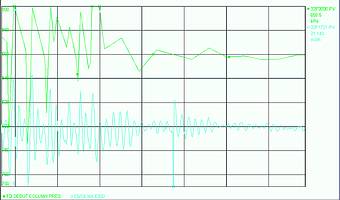
The solution that was implemented to resolve the above problem was a simple detuning of the control loop. The gain was dramatically decreased, while the integral time was left largely unchanged. The effects of this detuning can be seen in Figure 4. Investigation showed that there are very few high frequency disturbances on the pressure, and the slow tuning constants proved to reject the disturbances sufficiently. Since big pressure disturbances can be quite destabilising on the column, one does not necessarily want quick setpoint tracking. In this case, the setpoint of the feedback pressure loop is written down by an advanced controller once a minute, and slow setpoint tracking is acceptable. For these reasons, it was decided that the simple, cheap solution solved the problem sufficiently.
The response of the loop was tracked on a 6-day period to check the robustness of the new tune. These results are shown in Figure 5.
One of the recommendations that accompanied this detuning of the controls was to lower the operational pressure of the column. By decreasing the pressure setpoint, the potential for a differential to develop between the column and the reflux drum is decreased. The effect of this can be seen in the centre of Figure 5, where the pressure was increased for a period and the increased instability is apparent. This will however require new operating temperatures to be determined to achieve the same cut. This is a longer-term project and hasn't been finished by the time of writing the report.
Conclusions
The control of pressure in a column, by making use of a hot-vapour by-pass, often introduces unexpected problems into the stabilisation of the column. Through a combination of process and control understanding it was possible to solve the problem in this specific case. The combined effect of a control solution (detuning of the PID control) and the process solution (decreasing the pressure in the column) often leads to a superior and more sustainable solution. However, designing a control solution to eliminate the possibility of inverse response when designing the column is definitely the most desirable approach.
Michael Brown has encouraged input from others regarding interesting control loop applications that needed some improvement. This article was one such offering.
For more information contact Michael Brown, Michael Brown Control Engineering, 011 486 0567, [email protected], www.controlloop.co.za
Michael Brown is a specialist in control loop optimisation, with many years of experience in process control instrumentation. His main activities are consulting, and teaching practical control loop analysis and optimisation. He gives training courses that can be held in clients' plants, where students can have the added benefit of practising on live loops. His work takes him to plants all over South Africa, and also to other countries.
| Email: | [email protected] |
| www: | www.controlloop.co.za |
| Articles: | More information and articles about Michael Brown Control Engineering |


© Technews Publishing (Pty) Ltd | All Rights Reserved
 printer friendly version