

I have lost count of the number of times I have been told that flow loops are very simple things, that they are easy to tune, that you do not need a tuning package to tune them, that they can be tuned in a couple of minutes, etc. If this is true, then I must be remarkably unlucky to have found very few working well, in any of the hundreds of plants where I have performed optimisations.
I have also been told by an eminent advanced control engineer working in a petrochemical refinery that flow loops need not be tuned too well, as the speed of such loops will not affect the plant performance. This may be true in certain instances, but in general I completely disagree, and would stipulate that it is not good practice, particularly where these loops are often almost completely detuned.
To cite an example, I was recently optimising some controls at a plant. They were having trouble with a critically important airflow loop. The process is subject to frequent load changes and they also need to make setpoint changes from time to time. Several technicians had tried to tune it. When I tested the response, it took half an hour to get to setpoint after a 10% setpoint change. After being tuned correctly (and robustly), it took only 10 seconds! All that was wrong with it was the tuning.
During the past few years, I have also seen some flow loops with terrible mechanical problems. This article will deal with some of these.
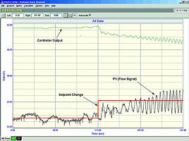
Figure 1 shows a closed loop test 'as found' on a flow loop where the operator was complaining that the loop was always unstable. Several of the instrument people in the plant had tried tuning the loop but could not get it to work properly.
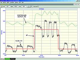
It is usually thought that if a loop is cycling, then the tuning is wrong. Most people immediately try and stop cycling by playing with the tuning. However, the fact that a loop is cycling does not necessarily mean that it has been tuned badly. There are many other reasons for cycling, including signal aliasing, hysteresis, interaction, slip-stick, and positioner problems.
Often one can get a pretty good idea of what may be causing the cycle by examining a recording of the cycle. In this case and as can be seen in the figure, the period of the cycle is quite long (varying between 20 and 50 seconds). One can immediately rule out tuning as the problem. If a loop is unstable (due to bad tuning) it cycles at the ultimate frequency of the whole loop, the period of which in the case of most flow loops is in the region of 6 seconds. Also, we can see that the PV is cycling in almost a square wave fashion, whilst the PD (controller output) is moving in a very distinctive triangular or saw-tooth wave. Also at the instant that the PD starts reversing, the flow also starts moving in the opposite direction.
This is a very distinctive pattern and is due to the fact that the valve is first sticking at a point where the valve is away from setpoint. The controller's integral term then starts ramping and continues until the valve's actuator has sufficient energy in it to manage to get the valve moving again. It then overshoots setpoint, and sticks again on the other side.
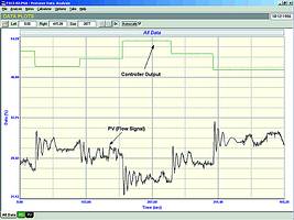
This has been described in a previous article as a 'stick-slip' cycle, which is normally caused by valve hysteresis. However, in this particular case it is caused by a different effect. The test shown in Figure 2 is the open loop test, where several equal steps are made on the PD. The response of the PV is of great interest. It can be seen that the valve overshoots considerably every time it moves. Unfortunately, this is not repeatable. There is a very large overshoot with a fast recovery on steps when the valve is opening. However, on closing, it overshoots and it then takes quite a long time before it recovers. In one case, which is the third step in the test, where the valve is to start closing, it first overshoots, and then undershoots. This cannot be seen in any of the other steps. The reason for the valve's behaviour could be caused by a variety of factors, including instability in the positioner, an undersized actuator, and many other things.
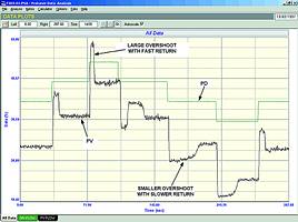
When a valve behaves in a non-repeatable fashion like this, good control becomes impossible. Cyclic behaviour in automatic is usually always encountered in cases like this, and this behaviour is what one sees in Figure 1.
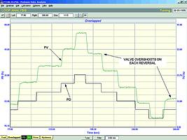
The second example is very similar, but the cycle is caused by a different phenomenon. Looking at the open loop test in Figure 3, one sees the valve overshoots on every reversal. In this case the valve stays in that position, and does not then move back in the opposite direction. We have called this phenomenon 'negative hysteresis' in the loop signature series. It is generally a sign that the actuator cannot cope with the static frictional forces (stiction) needed to be overcome every time the valve reverses. The positioner then pumps too much air into the actuator, so that when it finally does overcome the stiction it moves the valve too far.
The closed loop final test is shown in Figure 4. The closed loop cycle here is caused by the positioner overshooting set-point every time the valve reverses. The valve then sticks there whilst the output of the controller under the action of the integral term ramps until there is sufficient energy in the actuator to start the valve moving in the opposite direction again. The valve then overshoots setpoint, and sticks in that position.
This type of response is rather unusual insomuch as it is normally not seen exactly like this in most cases of negative hysteresis. It is definitely a type of stick-slip cycle, so that one must also assume that there is quite a slip characteristic in the valve when it starts moving on a reversal.
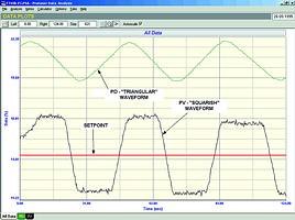
The third example is a flow loop in a fertiliser plant that was also extremely cyclic. Figure 5 shows a closed loop 'as-found' test. In the first half of the recording, it can be seen that the process was 'wavering' around about setpoint. When a step change was made on the setpoint, the loop actually went into a cycle. The reason for the cycle can be found from the open loop test shown in Figure 6. Every time a step change is made on the controller output, the flow responds with a cyclic under damped response that slowly dies out. It looks very similar to a response of a loop in automatic that has too high a gain in the controller. However, here the controller is in manual. The response is being caused by a positioner that is almost unstable.
This type of thing makes controlling a process impossible. No amount of tuning in the world can eliminate these problems. It also illustrates how important it is for a plant to have good valves. If problems such as these can occur on fast loops (like flow control loops), one would expect far worse problems to be encountered when trying to control the slower changing processes, like temperatures, with bad valves.
People often think I am exaggerating on the bad state of control in plants in these articles. However, I can assure you that this is normal. To illustrate this, I am writing this article whilst working on optimising a mining processing plant. The plant was commissioned only five months ago. The mine is wanting to put an advanced control system on top of the regulatory control layer, and the consultants realise that such a system cannot work efficiently unless the regulatory controls are operating properly, which is why I have been called in.
In the first three days, I have not found a loop working properly in automatic. A lot of loops have design problems on the process side, and some have poorly thought out control strategies. To make things worse I have not yet found a valve that is capable of performing decent control. (Luckily the plant uses a lot of variable speed devices for control flows and speeds of feeders. These loops can be optimised). However, there is one critical sump level control that the whole plant throughput is dependent upon. On this loop we found that the level measuring device freezes its reading a great deal of the time, so that operators often have no idea of the true level. The control valve is so bad that it only allows control of the flow through it between 30% and 50%. It will not allow flow to go outside that range. The operators spend a lot of their time trying to regulate the level by manually varying other parameters that can affect the level. There is no spare valve, although one has now been ordered on a priority basis.
It always seems strange to me that prior to my visits nobody seemed really aware of the state of these things. I believe operators are wonderful. Their job is to make product in spite of any difficulties they may encounter, and they generally achieve this by finding some way to get around the control problems. Ironically the controls were of course originally put there to help them, not hinder them.
For more information contact Michael Brown, Michael Brown Control Engineering, 011 486 0567, [email protected], www.controlloop.co.za
Michael Brown is a specialist in control loop optimisation, with many years of experience in process control instrumentation. His main activities are consulting, and teaching practical control loop analysis and optimisation. He gives training courses that can be held in clients' plants, where students can have the added benefit of practising on live loops. His work takes him to plants all over South Africa, and also to other countries.
| Email: | [email protected] |
| www: | www.controlloop.co.za |
| Articles: | More information and articles about Michael Brown Control Engineering |


© Technews Publishing (Pty) Ltd | All Rights Reserved
 printer friendly version