

I was recently requested to do a control performance audit on a mine situated in the Sahara Desert. The mine is run by expatriates from South Africa, Australia, USA, Philippines, France, Germany and Britain – really multicultural. I was amazed by the life these expatriates lead, typically working nine weeks on site, then three weeks off back home.
I had always believed that the companies running these plants made conditions on them as attractive as possible to keep staff happy, but that certainly was not the case on this mine. Accommodation consists of a tiny ‘hutch’ in a container, a bed, cupboard, small table and a few shelves. Not a lifestyle I would ever choose, even though the pay is remarkably good.
Anyway, enough of the diatribe and on to the problems at the plant, I had been called in because there was trouble with the controls. The control system was based on a well known make of European PLCs commonly used by many mining groups.
Extract taken from my report
The two important things that need to be done, particularly with control blocks on these PLCs, are:
1. Each control block must be triggered by a repeatable accurately timed interrupt, and this same time must be entered in the cycle time of the block. (Typically a 1 second cycle time is good for industrial control for various reasons). Integral and derivative values which are time dependent will be wrong if this is not done.
2. The control block must have both the SP and PV values normalised to a range of 0-100% on the actual inputs to the block. If this is not done and they are left in engineering units with ranges not 0-100% the proportional gain in the controller will be wrong.
3. Neither of the above things has been done correctly in the general programming of the PLCs, so that scientific tuning of most loops became very difficult, if not impossible. Even ‘trial and error’ tuning, based on people’s experience and feeling becomes impossible, as each loop’s controller can behave differently.
4. Normally one can investigate what has been done in the PLC programme and then apply corrections to each controller based on common factors, for example taking the measurement span into an equation to compensate for controller gain values. Unfortunately in this case it was found that individual control loops were not working the same way, and that the factors differ. The programme is extremely complex and we were not able to determine what the original programmers had done to make such a mess of things.
5. System integrators normally use their own functional specification on programming control blocks so that common routines and sub-routines apply on all loops. Such a specification did not exist on this mine. Also to complicate matters even further, many other people had subsequently worked on the programme so that not much commonality still existed. Not only did controllers in different PLCs operate differently, but it was found that controllers in the same PLC also could, and often did.
6. No wind-up protection had been programmed into the controllers. This needs to be done externally on this type PLC’s control block, otherwise the integral can wind-up into saturation if the PV cannot get to set-point for any reason. In certain cases this can take many minutes or sometimes even hours.
I recommended that in spite of the cost, it might well pay to get an expert programmer on that make of PLC to come to site and investigate and trouble – shoot the programme. And, if necessary, rewrite the control software so that all controllers operate correctly and in a common manner.
Practical examples
I have two interesting examples of loop problems found at that site. The first is a flow control loop where air is fed into the bottom of a flotation tank and causes bubbles to rise in the slurry, carrying certain valuable components in the slurry with it. (Refer also to Case History 105 which discussed this process in much more detail.)
The airflow is very important; in this case the mine was using an APC (advanced control) system to control the actual bubble size as measured by an analyser, the APC then determines the set-point of the airflow controller. Set-point signals like this, coming from an APC system, are generally always moving around fairly slowly and if the APC is to operate effectively, it is essential that the process variable (airflow in this case) follows the set-point with absolutely minimum variance.
Figure 1 is the closed loop test with the ‘as found’ tuning in the controller and a step change made on the set-point. (Note that the controller was in local set-point, ie, disconnected from the APC.)
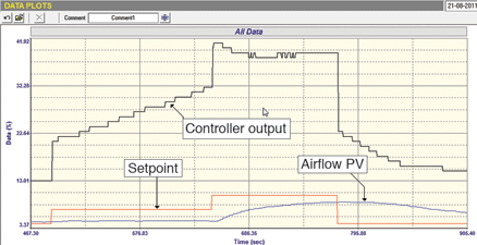
The following can be clearly seen:
1. The valve is displaying huge hysteresis as the PD (controller output) has to move back through about 20%, before the valve starts reversing.
2. The measurement is at far too low a value to be accurate or even creditable. The transmitter in use was a thermal type flowmeter, but I was unable to find specifications at the plant on its rangeability. However, it is unlikely any type of flow transmitter could give reliable, let alone accurate readings this low down.
3. The valve is also working far too close to seat; it is remarkable that it was able to give any control at all. As a rule-of-thumb, control valves should be operated above 20%.
4. The tuning was very bad with far too slow an integral for a flow loop.
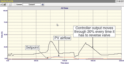
Figure 2 shows the final closed loop test performed with reasonable tuning values in the controller. This test is a wonderful example of the detrimental effects of hysteresis on closed loop control, with huge reversals being made by the PD under the influence of the integral action every time the controller needs to move the valve in the opposite direction. The figure was deliberately presented showing the whole 0-100% range, in order to illustrate how close both the measurement and valve are to zero. It was recommended that the valve should be replaced with a smaller one and that the transmitter be recalibrated with a much smaller span.
The second example concerns the problems the plant incurred in tuning the controller of an important tank level control. The control was extremely unstable with the level moving in a large cycle and with the output opening and closing the valve over a wide range. Weeks of trying to get the process under control had been of no avail.
The original tuning parameters that were found in the controller were: P = 15,0 and I = 3 200 seconds/repeat. Comparison of the two tunings will give an insight into why the loop was previously so unstable!
A short while later the plant shut down and it was possible to do a test on the controller to establish the real value of the 3200 seconds/repeat integral. It was in reality 290 seconds/repeat. How can PLC programmers get things so wrong?
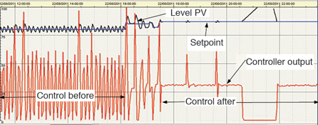
Figure 3 shows a section of the trend of this control loop taken from the plant’s scada before and after tuning. It shows the remarkably good control of the level (after tuning) and how quickly it managed to catch the two load upsets. (The pump on the outlet of the tank was switched off at one stage, which is why the controller’s output went to zero and the level up to the top.)
This example really shows how difficult it was for the plant technicians to try and tune with the controllers all working in a different way. As mentioned in several previous articles, I generally find at least 85% of controllers in PLCs set up incorrectly. These were about the worst I have ever seen!

Michael Brown is a specialist in control loop optimisation, with many years of experience in process control instrumentation. His main activities are consulting, and teaching practical control loop analysis and optimisation. He gives training courses which can be held in clients’ plants, where students can have the added benefit of practising on live loops. His work takes him to plants all over South Africa, and also to other countries. He can be contacted at Michael Brown Control Engineering cc, +27(0)11 486 0567, [email protected], www.controlloop.co.za
| Email: | [email protected] |
| www: | www.controlloop.co.za |
| Articles: | More information and articles about Michael Brown Control Engineering |


© Technews Publishing (Pty) Ltd | All Rights Reserved
 printer friendly version