

I have often written about the dearth of understanding of practical control, which is largely due to the generally purely theoretical teaching of process control at educational institutions. I have also mentioned that control is generally much worse in plants running their analog controls in PLCs (programmable logic controllers), as opposed to DCSs (distributed control systems).
PLCs are far more flexible in their programming than DCSs. In the DCS the manufacturers generally enforce a strict programming structure, which in fact protects the users from making errors, and more or less forces them to do things correctly. There is no such structuring in PLCs. Users can do anything they like, and very often they do things wrong. This was driven home to me again during the practical session in a recent training course I gave at a large mine.
The mine uses a popular make of PLC. In passing, it should be mentioned that it does make more sense in most mining applications to go the PLC route, rather than use DCSs. Apart from cost considerations, the digital I/O count is very much bigger than the number of analog loops. Many mining people also think that they do not need the features and sophistication of a DCS. However, this is incorrect. I have found that mining applications, in fact, often call for quite complicated control strategies generally available as standard in most DCSs. Many PLCs do not offer these features, and as a result the controls are sometimes severely compromised.
I have found it necessary the first time I go into a plant that uses PLCs for control, to test their PID blocks to ensure they are functioning correctly. In at least 60-70% of cases I find that in fact they are not right. In this mining plant both the proportional gain and the integral terms in the PID blocks were completely incorrect. (It is seldom necessary to check the D term, as it is hardly ever used, particularly in processes encountered in mining applications.)
If the proportional gain is incorrect, then this is often due to incorrect interfacing and/or scaling between the scada (Supervisory Control and Data Acquisition) and the PLC. If the integral term is wrong, it usually means that the person who originally programmed the PLC has not set up the triggering of the PID blocks correctly. Integral and derivative are completely time dependent. Therefore, the PIDs need to be triggered in the PLC by an accurate and repeatable timed interrupt, and the scan rate of the interrupt must then must be entered correctly in the PID block's parameter information area correctly.
In this case it was extremely difficult to correct the problem, as the original programming of the controllers had been very badly done, and the execution of the PIDs was performed in such a way that all the timing was completely dependent on the actual program scan time of the PLC. (PLC scan times are variable as they are affected by miscellaneous interrupts that can occur in the program from time to time). To change it completely would have virtually meant a major rewrite of the whole PLC program. Fortunately, the senior electrical and instrument technician in the plant was a bright and highly competent programmer, and he managed to write some clever software that gave reasonably repeatable PID execution times. (As a general rule, in practical control absolute accuracy to multiple decimal points is not at all critical.)
A couple of the loops that were examined are of interest:
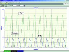
Figure 1 shows the performance of a slurry flow control loop on the 'as found' closed loop test. It can be seen that the loop was effectively completely unstable. Once the controllers had been set up correctly, and the loop tuned properly, it behaved very well. It is quite fascinating that one can find loops operating like this in working plants.
The second loop, which is the control of a secondary crusher, is an excellent example of how people can do things incorrectly on PLCs, and also how little understanding there is of practical control. Figure 2 shows the set-up of the crusher. Ore is fed from a bin to the crusher via a belt feeder equipped with a variable speed drive.
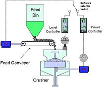
Crushers of this type are generally operated by controlling the level of the ore in them. However, in this case the crusher motors were undersized, and the motors tended to overheat and trip, particularly on harder ores. To try and prevent this the metallurgists had come up with a strategy so that the control of the crusher swapped over from the level controller to a power controller when the motor power exceeded a high limit. The problem with this was that under power control the level in the crusher had to drop to below 50% before there was any noticeable reduction in the power. (The power remained more or less constant once the level was above 50%.)
Apart from this being very non-linear, the crushing efficiency also dropped drastically at lower crusher levels. In actual fact we also quickly ascertained that in reality there was no real way that stable control could be obtained in the power control mode.
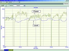
Figure 3 shows a closed loop test with the control swapping backwards and forwards between the power and level controllers on a cycle of about 2 minutes. As can be seen it is very bad. It is noteworthy that the mine has been trying for years to set the tuning of the controllers to get good control. (One of the common fallacies in process control is that 'all control problems can be sorted out by tuning'.)
Essentially, the problem is process related and is not a control problem. Either the crusher motors are underrated, or the crusher is not right for the application, and a solution cannot be obtained by trying to control both power and level (which in particular is unworkable in this instance).
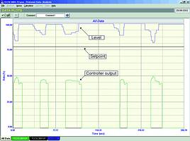
Another fault in the set-up of the control loop was that if the level in the crusher ever went too high, the belt feeder was stopped by literally forcing the output signal from the controller to zero. When this happened the programmer left the controller in automatic. This resulted in the controller output value winding up. In addition the dynamics of the level process had a very long deadtime of about 15 seconds, and an extremely large process gain for an integrating process of about 0,2 (equivalent to a tank retention time of about 5 seconds!). This means that once the level started moving, it could change extremely quickly, making control very difficult.
The correct tuning required for these dynamics results a very small gain, and long integral. Therefore, when the interlock was released, the integral had wound up the output so far that huge process bumps were caused with big overshoots or undershoots. In this case the overshoots were so large that they were causing the trips to occur again. As a result the control loop was effectively cycling on and off. This is shown in Figure 4. A better approach in a situation when one must force the controller's output to a different value, is to put the controller in manual so reset wind-up cannot occur. There are also other solutions.
I have come across this type of interlock numerous times in systems controlled by PLCs. The people who do this program have little understanding of controllers, and of the damage that can be caused to control systems by incorrectly interfering with the operation of a control loop. In one remarkable case on a ferrochrome furnace pressure control, the PLC programmer had no idea how to achieve balanceless, bumpless transfer between automatic and manual, and had programmed the controller so that when it was switched to Automatic it first set the controller's output to zero. On that particular process, it caused an explosion, which ruptured all the emergency blowout disks, resulting in a direct cost to the plant of over R100 000 - not to mention 72 hours lost production.
Another interesting thing discovered by accident on this same loop in the mine, was that when the PD (controller's output) varied from 18-38%, the feeder belt speed varied between 1 and 100%. This is analogous to using a 5-times oversized control valve in a flow control application. Apparently, one of the metallurgists had felt that faster control could be obtained if the speed of the hydraulic variable speed drive was made faster. To achieve this the plant had replaced the hydraulic control valve on the drive with a larger one. This meant that no control action was being achieved over 80% of the controller's output range. This type of thing can also badly affect the control.
In general it is apparent that people need to get a much better understanding of the practicalities of control. It is also essential that optimisation of control systems can only be successful when the various departments including process experts and instrumentation and control people work together with a mutual understanding of the objectives and requirements for the control.
Addendum
I was finishing off this article one evening after spending a day optimising control loops in a leading manufacturing company's paint plant. The control of the process is critical. If the temperature deviates from setpoint by more than one degree centigrade, the product worth many tens of thousands of rands is actually scrapped. The control is accomplished using a well-known make of German PLC, and the programming was done in Germany. I was horrified to learn that there was no way that one could place the controllers into manual. The control blocks had been blocked from access, and there was nobody in South Africa who knew how to get in to modify them. I can understand that the designers didn't want plant operators to be able to normally run the plant in manual, but how on earth did they think that the technical specialists would be able to tune the controllers? It is essential to be able to make step changes in manual when performing loop analysis and tuning! Once again it shows that worldwide, people doing regulatory controls on PLCs have very little knowledge of what they are doing.
For more information contact Michael Brown, Michael Brown Control Engineering, 011 486 0567, [email protected], www.controlloop.co.za
Michael Brown is a specialist in control loop optimisation, with many years of experience in process control instrumentation. His main activities are consulting, and teaching practical control loop analysis and optimisation. He gives training courses that can be held in clients' plants, where students can have the added benefit of practising on live loops. His work takes him to plants all over South Africa, and also to other countries.
| Email: | [email protected] |
| www: | www.controlloop.co.za |
| Articles: | More information and articles about Michael Brown Control Engineering |


© Technews Publishing (Pty) Ltd | All Rights Reserved
 printer friendly version