
In the last issue of SA I&C we looked at considerations during the installation of load cells, the significance that the associated cabling has, and precautions to be taken when performing arc welding in the vicinity of a load cell installation. This month we conclude this informative series with a discussion on lightning protection, internal and external electrical protection and maintenance. There is also a handy ‘do’s and don’ts’ table that summarises many of the aspects discussed in this five-part series of articles.
Lightning protection
Modern weighing systems rely heavily on high performance electronic components, but the features that make this possible also make these components more vulnerable to the disruption and damage that can be caused by lightning or overvoltage in general.
Investigations indicate that a lightning strike within a 300 m radius of the geometrical centre of the site will definitely have a detrimental effect on the weighbridge. Nor is such damage confined only to earth strikes, since cloud-to-cloud strikes are equally capable of producing an electromagnetic pulse (EMP) of sufficient strength to cause damage.
In most cases, the actual load cell damage is a direct result of a potential difference, well in excess of 1000 volts, between circuit and housing.
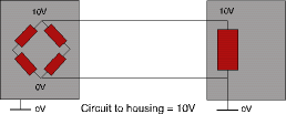
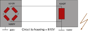
It should be recognised that a high potential difference between housing and load cell circuit can be caused by:
* A rise of local earth potential when a lightning strike is dissipated through the ground.
* Severe overvoltages or electromagnetic pulses via the main power supply.
The damage in both cases might result in a complete burn out of the component, but this is not always true. It is possible that only a part of the load cell's circuit or one of the strain gauge's glue layers is damaged. As a result, the scale starts to drift and/or will not hold its return to zero. Sometimes these problems appear weeks after the actual lightning strike!
It is obvious that a high level of protection against lightning strikes can only be established if the complete system is protected. The decision to protect a system or part of a system should be based on:
* The location (urban area or open field).
* The average ground flash density (ask for statistics at the appropriate institute).
* The costs incurred during a breakdown period.
* The expenses for the replacement of parts and workmanship.
* The insurance company requirements (or premiums!).
Protection can be considered in two stages; external and internal.
External protection
External protection entails bonding the steel roof of the cabin where the indicator is located or any nearby structure or a high protection mast in such a matter as to provide a preferential point of discharge and safely conduct the surge to earth via conductors.
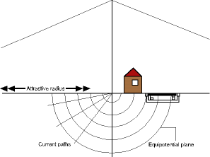
In fact, considerable controversy surrounds such external protection. A weighbridge or, in general, a scale is not an attractive point for lightning to strike, but an 18 m mast has an attractive radius of 22 m. Lightning which might otherwise have struck a building or tree 55 m or more away will now be captured to produce a current surge to ground within the very neighbourhood of the weighbridge!
Unless very stringent precautions are taken such a surge will produce an electromagnetic-induced pulse that will undoubtedly cause severe damage to the weighbridge.
Internal protection
Internal lightning protection sets out to provide potential equalisation throughout the whole system by defining a central point about which all the electrical systems can float or by using surge protection devices (SPDs).
Surge protection devices are designed to control line-line and line-earth voltages to levels acceptable to the equipment. An SPD incorporates combinations of gas-filled discharge tubes for high current surge diversion and Zener diodes for secure voltage clamping with minimal leakage. For AC power applications, varistors are often used because of their higher power absorption capability. Most SPDs are connected in series, similar to shunt diode barriers for intrinsically safe systems.
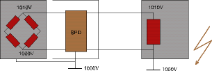
Any device that works by diverting large currents to a local ground must have a low impedance connection to that ground. This means that the bonding connection must be of low resistance (well below 0,5 Ohm), short in length and as direct as possible without sharp bends. Earth connections need to be verified at least twice a year and all connections should be coated with a good antioxidant grease.
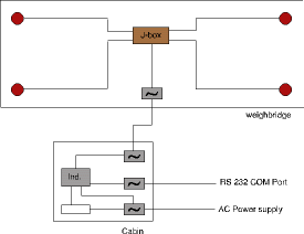
Any external connections such as AC power lines, communication ports and signal/excitation cables are potential sources of surges or transients. Central to the provision of lightning protection is therefore the installation of an SPD at all external connections:
Maintenance
Maintenance is often overlooked or ignored by both load cell users and service companies. However, the regular service and maintenance of load cells in a weighing system will greatly improve their long-term reliability and performance as well as greatly reduce their sensitivity to corrosion. Maintenance inspections can be divided into two categories:
* Routine: Performed at periodic intervals, they include the removal of any material or debris build-up from around the load cells and mounting fixtures. Serious damage can occur to the load cells if mounting systems do not function correctly. Any damage or degradation of surface coatings should be remedied and all cables and junction boxes should be checked. To minimise the effects of flooding, any drainage systems in the pit should be free from debris. Where required, regular wash-down of the load cell should be carried out to prevent chemical attack.
* Ad hoc: Made immediately after any adverse or unexpected events such as flash floods, gales, seismic activity or electrical storms. In general, careful consideration must be given to any reason for failure. If this has occurred as a result of ingress of water or chemicals, then continued deterioration of any other load cell(s) in the system can be expected, resulting in mechanical failure. This failure can have serious safety and cost consequences. The load cell should always be removed with care, and a label attached with comments describing the problem or mode of failure. The cable should never be cut at the gland to facilitate removal, as load cells cannot be tested without their cables. (Remember that in the case of three-wire installations, the wires form part of the calibrated instrument).
Do's and don'ts of load cells - summary
Load cell selection and design
* Do select the right load cell for the application in terms of type and environmental compatibility. Do choose the right capacity.
* Do consider the required accuracy class.
* Do consider all environmental aspects before making the final choice (whether they are always or occasionally present at the place(s) the load cells will operate).
* Do provide for any additional environmental protection at the design stage.
* Do design-in adequate over/under load protection as well as protection from other mechanical damage (eg, physical abuse, rodent problems).
* Don't make the choice based only on price - cost of ownership is more important.
* Don't allow load cells to operate above their rated capacity.
* Don't over specify - look at overall system limitations on accuracy (eg, mechanical pipe work, vibration etc).
* Don't ignore the hurricane or flood that comes once every two or three years.
* Don't build in water/debris traps.
* Don't assume 'it' will never happen, and never use the load cell as a mechanical fuse.
* Don't forget to provide adequate protection for the load cell cable, near the load cell if possible.
Installation and fitting
* Do use dummy load cells prior to installation.
* Do store and handle load cells carefully prior to and during installation, and try to keep copies of the Certificate of Calibration in a safe place. Check load cells before fitting for correct model, capacity, thread combination, etc.
* Do check that any threaded fittings screw smoothly into the load cell before final assembly.
* Do use high quality bolts with the recommended torque.
* Do check that adequate and accurately fitted mounting surfaces are provided.
* Do use care when tightening mounting bolts and restraints such as tie-bars.
* Do use lock nuts appropriate on threaded fittings, especially if vibration is present.
* Do check cable colour code for load cell prior to connection - Revere Transducers has two basic colour codes.
* Do use good quality connecting terminals/junction boxes. Solder joints if possible.
* Don't carry out electric welding near load cells, if possible.
* Don't forget to check specific storage and operating temperature ranges for the load cells.
* Don't ever carry load cells by their cables!
* Don't force bolts or other threaded assemblies.
* Don't use mounting bolts to pull uneven surfaces together - use shims as appropriate.
* Don't use excessive force when fitting/tightening mounting bolts or hardware, especially on low capacity cells.
* Don't twist 'S' cells when tightening threaded fittings.
* Don't cut load cell cables unless necessary - performance may be affected.
* Don't allow moisture to get at any interconnections.
* Don't allow the load cell to be the electrical link between ground and the metal weigh structure.
Maintenance
* Do regularly inspect load cells and weigh systems, especially after extreme weather conditions (electrical storms, flooding, seismic activity, etc) and also before and after the seasons.
* Do check for corrosion damage to the load cell and mounting hardware. If practical, carry out cleaning and any remedial work (paint or other protective coating) before it is too late.
* Do give special care and attention to critical areas of the load cell such as metal bellows, seals, etc. Those features are important in the operation and performance of the product.
* Don't allow build-up of debris around the load cell or mounts.
* Don't allow any drains to become blocked with leaves or other debris.
* Don't disconnect and just re-calibrate one or more load cells in a system if they cease to function. Mechanical failure may have catastrophic effects.
Finally
* Do remove the load cell with care and attach a label with comments relating to the problem or mode of failure.
* Do return a copy of the Certificate of Calibration with the load cell, if available.
* Don't cut cable at the gland to facilitate removal - load cells cannot be tested without their cables!
| Tel: | +27 10 595 1831 |
| Email: | [email protected] |
| www: | www.instrotech.co.za |
| Articles: | More information and articles about Instrotech |

© Technews Publishing (Pty) Ltd | All Rights Reserved