

In the last issue of SA I&C, environmental protection of load cell installations was discussed, ending with an explanation on how cell construction and installation plays a part in the installation’s ability to best stand up to the rigors of the elements. This issue we take a closer look at the mechanical installation of the load cells, the methods for attaching cables, and the correct manner in which to go about performing any electrical welding near the load cells.
Installation
The installation of load cells into a practical field application requires careful attention if the system is to be safe and accurate. It is a common misconception that a load cell can be considered as a solid piece of metal on which hoppers or platforms can be supported. The performance of a load cell depends primarily on its ability to deflect repeatedly under conditions when load is applied or removed. Furthermore, if more than one load cell is used then the deflection and output of each individual cell should be similar on each load point. To satisfy the above requirements, load cells are mainly used in conjunction with special mounting systems rather than being mounted rigidly between platform/hopper and foundation.
Load cell supports should be designed to avoid the following effects to the load cell:
* Lateral forces.
* Bending moments.
* Torsion moments.
* Off centre loading to the cell.
* Vibration to the load cell.
These effects not only compromise the performance of the load cell, but they can also lead to permanent damage.
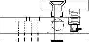
If major load movement is anticipated, stay rods should be used to restrain a platform (weighbridge) or vessel. Stay rods are installed horizontally and should not transfer any forces to the vessel or scale in the vertical direction, while having sufficient strength in the horizontal direction to be able to absorb side forces. The length of the rods should be chosen as long as possible, as this has a favourable effect on reducing vertical forces.
The arrangement of the stay rods depends on the plan view geometry of the structure. In most cases four rods give the best results.

Stay rods provide stability and accuracy, especially for systems with agitators. They should be installed carefully (exactly horizontal) and without any stress.
Stay rods should not be confused with safety rods, which are installed similarly, but provide a different function. Safety rods are left loose during normal operation. They are an extra safety feature in the event of wind forces, seismic activity or mechanical failure of mounts or load cells. Safety rods are strongly recommended for those systems where one of the above events could seriously affect personnel safety or where one of the above events could lead to extensive damage.
In order to assure performance, load cells should be placed on exactly the same horizontal level. Never use mounting bolts to pull uneven surfaces together; shim plates should be used as appropriate. The preferred orientation of the load cell depends primarily on its design. The load should always be transmitted vertically through the load cell in the way that it was designed to measure force.
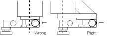
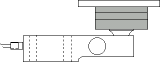
S-type load cells should be mounted in such a way that side forces are reduced to a minimum; they should never be mounted rigidly (even only at one side) between the structure and hopper. The load cell must be orientated in such a way that the cable entry does not affect weighing accuracy.
In terms of safety, attention should be paid to use the full length of thread, while consideration should be made to provide an external back up system.
To prevent load cells from being damaged during installation, it is strongly recommended to use dummies or mounting assemblies that can be 'locked'. Load cells should be handled with care, especially those with a low rated capacity or with metal bellows construction. Single ended beam load cells are subjected to a momentum and require high quality bolts for safe operation. The amount of torque on these bolts is specified and should be met to achieve the maximum performance.
Load cell cables
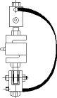
Special attention should be paid in preventing the load cell cable from being damaged during and after installation. Never carry load cells by their cables and always provide dripping loops to prevent water from running directly into the cable entry.
Load cells are produced with a four or six-wire cable. A four-wire cable is calibrated and temperature compensated with a certain length of cable. The performance of the load cell, in terms of temperature stability, will be compromised if the cable is cut; never cut a four-wire load cell cable!
A six-wire load cell cable has two additional wires, which can be used to actually measure the excitation voltage at the load cell in order to feed this information back to the indicator. A six-wire load cell is not part of the load cell's temperature compensating system and can be cut to any desired length. However, it should be recognised that the parallel connection of multiple six-wire load cells results in an equal potential difference over all cells. All load cell cables should therefore be shortened to the same length.
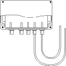
Junction boxes
The junction box is an essential part of the system and should be protected to at least IP65 or NEMA 4. Select the location of the junction box based on the environmental conditions; not on the ease of installation. During the installation ensure that no moisture enters the load cell cable before and during installation. A bag of drying agent (silica gel) may be enclosed to absorb moisture, however, the drying agent should never make contact with any non-insulated wiring in the box.
Use junction boxes with high quality terminals or use solder connections. The components used for corner correction should be absolutely temperature stable.
Welding
Avoid electric welding after installation of the load cells. If welding is necessary and the load cells cannot be removed, then disconnect each individual load cell cable from the junction box or measuring device. Place the earthing clamp electrode of the welding apparatus in the close proximity of the weld to avoid a current path through the load cells. Furthermore, connect a flexible copper lead over each load cell.
| Tel: | +27 10 595 1831 |
| Email: | [email protected] |
| www: | www.instrotech.co.za |
| Articles: | More information and articles about Instrotech |


© Technews Publishing (Pty) Ltd | All Rights Reserved
 printer friendly version