

During the two-day practical part of a course held recently in a large South African chemical plant, it was found that none of the valves had positioners on them. This is very unusual these days.
The primary purpose of a positioner on a spring and diaphragm operated valve is to minimise hysteresis, and to ensure that the valve stem gets reasonably close to the position as requested by the controller output (PD). Hysteresis on valves without a positioner can normally be as high as 3 to 5%. This figure should be 1% or better when a positioner is used. In the early days, positioners were often thought to lead to instability in fast loops. However, these days reputable valve manufacturers ensure that their positioner-valve combinations are stable.
The plant where the course was being held had rather complex processes, which required good controls for optimum performance. As mentioned many times in these articles, good control performance cannot be obtained if valves do not operate properly. This is even more important on slower processes. Therefore, it was not surprising to find that the vast majority of the controls analysed during the course were performing dismally.
The example discussed in this article is a liquid flow control with extremely high valve hysteresis.
The initial closed loop 'as found' test is illustrated in Figure 1. In this type of test, setpoint changes firstly up and then down are performed on the controller, which is in automatic. The control parameters as found in the controller were P = 0,8, and I = 20 seconds/repeat. With experience, one can immediately judge that these are not very good tuning parameters for liquid flow control.
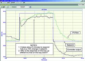
At the start of the test it can be seen that the process is not exactly on setpoint, and that the PD (controller output) is also remaining fairly constant. This is an indication confirming that the integral setting in the controller is far too slow. The process response to the step-up in setpoint shows an initial fast rise with a little overshoot followed by a slow ramp up to setpoint taking some 3 minutes. This is a typical response of a flow loop with too high a proportional gain, and too slow an integral setting.
The step-down in setpoint is very interesting, as it appears to be completely different to the previous response on the way up. Surely a flow loop should have pretty similar responses to setpoint changes up and down? The reason that there is a difference is because there is a valve problem. On deeper inspection of the response it can be seen that the controller output dropped immediately on the setpoint change, but the flow did not start moving for nearly 10 s. This is far too long to be the normal deadtime of a flow loop, which is generally much less than 2 s. This indicates that there is excessive hysteresis in the valve and that the output of the controller had to drop a certain amount to get the valve to start moving in the reverse direction. In fact the output had to drop nearly 10% before the valve started moving and only then did the flow start coming down.
The open loop test confirmed the fact that the valve did in fact have more than 10% hysteresis. Figure 2 shows a portion of the test where the valve direction is reversed, and it is necessary to move the output just over 10% before the flow starts cutting back.
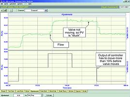
10% hysteresis in a valve is really unacceptable. As mentioned above, a valve without a positioner should not have hysteresis exceeding 3%. So although this valve is really bad, a positioner would have helped to reduce the hysteresis considerably.
When tuning a process with hysteresis on the valve it is very important that one chooses a step to tune on which represents the true process response, and not one where the size of the response might be affected by hysteresis in the valve. Typically, many tuning packages and self-tuning controllers use a single step for the tuning. If that step was the first step after the valve had reversed, a certain amount of the energy supplied by the actuator might actually have been absorbed in getting the valve to move through any hysteresis, thus limiting the size of the response. The tuning parameters obtained from such a step may cause the response in automatic to be too cyclic or even unstable.
The other thing to remember when tuning a loop with excessive hysteresis in the valve is to choose a response that will result in minimum valve reversals on changes in load or setpoint. If for example, one was to tune for a quarter amplitude damped response, then theoretically the valve would reverse at least 8 times on every setpoint change. If this was to take place on a valve with excessive hysteresis it would literally take many minutes, if not hours, for the controller integrator to reverse the valve each time, as the output has to move fully through the hysteresis band before the valve can move. Therefore, it would be preferable to choose a critically damped response, which avoids reversing the valve completely on a setpoint change.
As a point of interest, we never advocate quarter amplitude damped tuning for a variety of good reasons. Amongst them are that such a response is too close to instability in real-life plant conditions where changes are may frequently occur. Also is it a good idea to reverse a valve 8 times every time you move it? It's certainly going to wear out pretty quickly. Next as mentioned above, if there is hysteresis on a valve (and most valves do have even a little hysteresis), reversing it actually slows down the response and increases control variance. In reality, quarter amplitude damped tuning is not practical.
Figure 3 illustrates the final closed loop test with tuning of P = 0,2, and I = 1,5 seconds/repeat. The tuning is close to critical damping and the vastly improved response to setpoint changes in both directions can be clearly seen. The response time even with such a relatively slow tune is now only 25 s! Note that the new tuning incorporates an integral setting, which is about 14 times faster than the original setting.
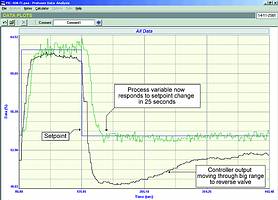
It is quite interesting to observe that even with the slow tune that there was a slight negative overshoot after the setpoint change down, and it can be seen how long it took for the controller output to integrate back-up before getting the valve to reverse and hence return the flow to setpoint.
Michael Brown Control Engineering
(011) 486 0567
Michael Brown is a specialist in control loop optimisation, with many years of experience in process control instrumentation. His main activities are consulting, and teaching practical control loop analysis and optimisation. He gives training courses that can be held in clients' plants, where students can have the added benefit of practising on live loops. His work takes him to plants all over South Africa, and also to other countries.
| Email: | [email protected] |
| www: | www.controlloop.co.za |
| Articles: | More information and articles about Michael Brown Control Engineering |


© Technews Publishing (Pty) Ltd | All Rights Reserved
 printer friendly version