

Following on the theme of Case History 135, here is another example of what a really bad valve can do to contribute to problems in control loops.
The example is of a loop controlling the reflux flow on a distillation column. Figure 1 shows the ‘as found’ closed loop test where step changes of set-point are made with the original tuning parameters left in the controller.
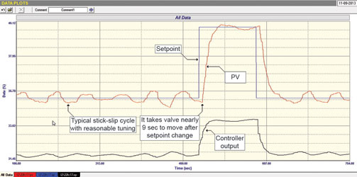
Closed loop test
The test shows several things:
Firstly when the set point is kept constant, the loop is in a continuous cycle. Most people would say that the tuning is bad, however there are many other reasons why closed loop controls can cycle, and most of these are due to valve problems.
If a loop cycles due to bad tuning, which would be the case for example if there was too much proportional gain in the controller, or too fast an integral, then usually it will cycle at a frequency close to the natural resonant frequency of the loop. A flow loop using a pneumatically actuated valve and which has got unstable tuning, will typically cycle at frequency of around 0,2 Hz, which is a period of about 6 seconds. In this case the period of the cycle is close to 45 seconds. Furthermore, if instability is due to bad tuning then there is normally a big overshoot of the PV (process variable) on a step change in SP (set-point). Therefore, this cycle is definitely not caused by bad tuning.
The next distinctive feature of the cycle is the shapes on the PV and that on the PD (process demand, another name for controller output). It can be seen that the PV is moving up and down in a ‘square’ waveform, whilst the PD is moving in a type of ‘saw-tooth’ wave. This is because the valve is sticking and then the integral term in the controller ramps the PD up (or down) until the valve actually breaks away and starts moving. The valve then overshoots, so the PV goes beyond the SP. This type of cycle is typically known as a ‘stick-slip’ cycle.
Stick-slip cycles arise from various causes ranging from inherent valve issues though to positioner problems – more on this a little later.
The second problem shown up by the test is the apparent dead time that occurs when the SP change is made, until the PV actually starts moving. The PD responds immediately when the SP moves, but the PV only moves a lot later. In this case the measurement of the dead time is about eight seconds. In general flow loops incorporating pneumatically actuated valves have a maximum dead time of about two seconds. Eight seconds is extremely long and indicates that the valve sticks when being reversed. The PD, which is moving relatively slowly when the loop is in automatic, has to move over 1% of its span before there is sufficient energy in the actuator to overcome the stickiness.
A third possible problem indicated in the test is that the amplitude of the cycle on the PV is larger than that on the PD. This could indicate that the valve is oversized, which will be checked again on the open loop test, discussed after this.
The other thing that can be seen is that the tuning looks quite reasonable. Although hard to see because of the stick-slip cycle, it can be seen that the PV gets to a new SP after a step change relatively quickly and without too much overshoot.
Open loop test
The next, and most important test from the analytical and tuning point perspective, is the open loop test where several step changes of the PD are made with the controller in manual. This is shown in Figure 2.
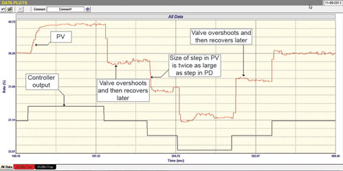
The first thing we see is that the valve overshoots each time it reverses. We call this well known phenomenon negative hysteresis. Unfortunately, this type of hysteresis is a very bad thing as it may, and usually does, result in uncontrollable cycling of the loop, exactly what has occurred in this case.
There are two common causes of negative hysteresis:
* Undersized actuator with insufficient power to get the valve through the static friction that reoccurs every time a valve is reversed.
* Positioner problems.
In this particular case one can see that on reversal the valve overshoots and then after a period the positioner tries to get the valve to return to the correct position. On many of the other steps with the valve moving in the same direction, it also overshoots and the positioner tries to bring it back again. These actions would indicate that the positioner has not been tuned properly, and it has too much gain in it. However, with the large dead time existing when reversing the valve in automatic, it may also indicate that the actuator is too small for the job.
The second thing that the test confirms is that the valve is about twice oversized. This is seen from measuring the process gain which is the size of a PV step divided by the size of the same step on the PD, with both measurements being in percent of span. A perfectly sized flow control valve would have a process gain of one. However, in real life one doesn’t want to size a valve too close to a unity process gain, as it doesn’t allow room if you ever need larger flows. Therefore most people who size valves properly usually allow a safety factor of 50-60%.

An oversize of two is not too serious. However, one must remember that as described in various articles in my Loop Signature Part 1 series, oversized valves increase control variance in direct proportionality to the oversize factor. Also any cycling, such as in this case, will cause the amplitude of the cycle to be increased by the oversize factor.
Once again we see what an important role is played by the valve in control loop performance.
Michael Brown’s next course series in Johannesburg will take place on 25 July.
Michael Brown is a specialist in control loop optimisation with many years of experience in process control instrumentation. His main activities are consulting, and teaching practical control loop analysis and optimisation. He gives training courses which can be held in clients’ plants, where students can have the added benefit of practising on live loops. His work takes him to plants all over South Africa and also to other countries. He can be contacted at Michael Brown Control Engineering cc, +27(0)82 440 7790, [email protected], www.controlloop.co.za
| Email: | [email protected] |
| www: | www.controlloop.co.za |
| Articles: | More information and articles about Michael Brown Control Engineering |


© Technews Publishing (Pty) Ltd | All Rights Reserved
 printer friendly version