

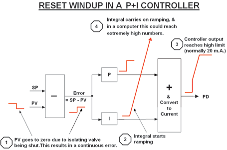
The purpose of the integral term in the controller is to eliminate the control error. However, the problem with the integrator is that it never stops trying to eliminate the error even in circumstances where the error cannot be eliminated. A good example of this is what is known as ‘integral wind-up’.
Reset or integral wind-up occurs when a continuous error exists which cannot be eliminated. To take an example, imagine that an isolating valve in series with the control valve is accidentally closed, and the controller is left in automatic. At this point let us imagine that the PV (process variable) goes to zero. The integrator in the controller will immediately start integrating to try and eliminate the error. This will result in the PD (controller’s output) increasing at the ramp rate of the integrator. As the error cannot be reduced, this will continue until eventually the PD reaches a maximum limit (normally set to 20 mA in most controllers).
However, it must be remembered that in theory, the integrator’s output will continue to carry on ramping for as long as the error exists. In reality, in the old days of pneumatic and electronic analogue controllers, this could only continue until a physical limit such as air supply pressure, or a bus voltage, was reached. At this point it was said that the integrator was ‘saturated’ or fully ‘wound up’.
The situation is different in a digital computer. The integral is now not a voltage or pressure, but a number, and modern computers can deal with extraordinarily high numbers. Therefore, unless the controller manufacturer does something about it, the integrator could carry on virtually until the output reaches a value close to infinity. This is illustrated in Figure 1.
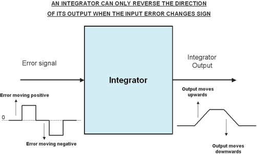
Eventually, when the process is restarted and the isolating valve reopened, fluid will flow through the fully open control valve. The PV will then start rising towards setpoint. However, due to the nature of an integrator, the PD cannot start reducing, and hence the control valve cannot start closing, before set point is reached. Figure 2 helps explain this. Essentially the integrator’s output cannot be reduced until the error signal on its input changes sign. This is because the integrator’s output will always rise as long as any positive error exists. If the error reduces to zero, the integrator’s output then remains constant. It can only start moving down after a negative error signal occurs. This means that the integrator can only start responding again once the PV has moved through the set point.
If the integrator has wound up, it means that it may take a long while for the integrator’s output to drop far enough to allow the PD to start moving down again, and at that point it would allow the control valve to also start closing. By this time an enormous process overshoot could have occurred. At a recent course I was presenting, one of the delegates, an instrument and control foreman on a gold mine, said that he now could understand why one of their controllers took up to 11 hours to unwind after a plant trip!
To overcome this wind-up problem, some of the controller manufacturers incorporate a strategy, often referred to as ‘anti-reset wind-up’, to prevent the integral from winding up. The method used varies from manufacturer to manufacturer, but most of them ‘freeze’ the integral unit’s operation when the PD reaches low or high limits (generally at 4 and 20 mA). At this point, the output of the integrator remains constant at the last calculated value, and does not carry on winding up.
This method of anti-reset wind-up still does not completely prevent overshoots, as again the integrator cannot start decreasing until the error actually reverses at the point the PV reaches setpoint. However, the overshoots will be much smaller than they would have been if no anti-reset wind-up had been employed.
One must also be aware that many manufacturers, particularly of PLC systems, do not provide this feature. One of the most commonly used PLCs in South Africa does not incorporate it. Users have to program it in themselves, but as no one really understands their controllers, I have never seen it done in a plant prior to my arrival.
External anti-rest wind-up
There are certain other situations where it is also important to be able to freeze the integral from an external signal. This is sometimes known as ‘external anti-reset’ wind-up. A particular example of this is where multiple controllers are connected to the same valve, as in the case of cascade control systems.
In a cascade control systems, the master controller’s output feeds the setpoint of the slave controller. The slave loop is usually much faster than the master. If the slave’s output reaches a limit, then its anti-reset wind-up will freeze the integral, but the master controller may still carry on integrating pushing its output further. To prevent this, a signal must also be sent to the master to freeze its integral as soon as the slave’s integral is frozen.
General rules
As a general rule, integral action should also freeze when further movement of the controller’s output can have no further effect on the control. In particular in every case of an oversized valve, a limit should be placed on the controller output to prevent it opening past the point where it cannot have further effect on the PV. This will help prevent both reset wind-up, and valve wind-up.
For example, if you have a valve that is four times oversized, and if it is properly calibrated (stroked), then when it opens to 25%, the measurement will reach full scale. One should therefore not only freeze the integral at this point to prevent reset wind-up, but also prevent for the valve from opening any further, which would cause the valve to wind-up. (This is something I have never come across in any course or book on control, yet it is something that seems very obvious, as every plant has many oversized valves in it.)
A very good example of how long it can take to ‘unwind’ a valve before it can affect the control is shown in Figure 3. This closed loop test was done at a mine in Namibia on a flow control loop.
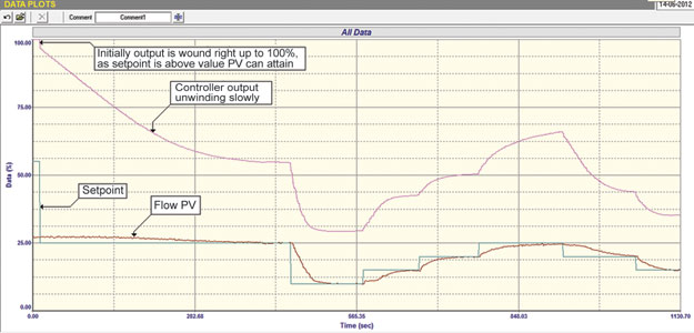
At the start of the test the setpoint was much higher than the PV as the pump pressure was limited. This condition of limited flow is normal on this process, and it never gets higher, but the Operators tend to push the setpoint up way past the point where the flow can get to, in an effort to get it to achieve the biggest possible flow. Thus the valve winds right up past the point where it can have any effect on the control. Please note that anti-reset wind-up was in fact programmed into the controller and was previously activated when the controller’s output reached the high limit of 100%.
As can be seen in the figure, the setpoint was then stepped down to just below this maximum flow value, and it can be seen how slowly the integral moves the valve down to the point where it can start affecting the control. Also as can be seen in the figure, after the valve started limiting flow, the control of the flow below the maximum flow point, was reasonable if slightly slow. A high limit was then placed on the controller output just above the point of maximum flow to prevent wind-up of the valve and the integral.

To finish off it can be very important to ensure the integral component of the controller is prevented from moving the controller’s output when it can have no further effect on the control.
Michael Brown is a specialist in control loop optimisation with many years of experience in process control instrumentation. His main activities are consulting, and teaching practical control loop analysis and optimisation. He gives training courses which can be held in clients’ plants, where students can have the added benefit of practising on live loops. His work takes him to plants all over South Africa and also to other countries. He can be contacted at Michael Brown Control Engineering cc, 082 440 7790, [email protected], www.controlloop.co.za
| Email: | [email protected] |
| www: | www.controlloop.co.za |
| Articles: | More information and articles about Michael Brown Control Engineering |


© Technews Publishing (Pty) Ltd | All Rights Reserved
 printer friendly version