

Further to my requests in this magazine for people to contribute control experiences of their own to these Case History articles, I am very pleased to introduce this two-part article by Etienne Wannenburg on boiler drum level control.
Etienne attended one of my courses a few years ago, where one of the subjects covered was how to deal with negative leads such as found in boiler drum level control (refer part 2-22 and 23 in my Loop Signatures series). This excellent article shows how well he has applied the teachings.
Introduction
Steam drum level is one of the major causes of boiler trips and downtime. Affected by the phenomena of swell and shrink, it is a difficult parameter to control accurately. Babcock conducted a study to determine the optimal configuration for steam drum level control, the basic process and analysis are the subject of this article.
Boiler circulation
In natural circulation boilers the steam drum is used to separate steam from water by scrubbers and other mechanical equipment. Once the steam is separated it flows to the superheated and main steam equipment with the outflow replenished by adding feed water to the drum.
Natural circulation within the boiler causes the feed water to flow from the steam drum through the down-comers to the boiler furnace. When the water reaches saturation temperature it flows back to the steam drum due to a change in density, steam and water are again separated in the steam drum and the cycle continues.
Swell and shrink reaction
Steam drum demand is controlled by the downstream process (eg, a turbine) via downstream equipment that regulates the steam flow based on the load. When the load changes, boiler steam drum pressure is affected.
The change in pressure changes both the density and boiling point of water in the boiler circuit, which causes the level in the steam drum to increase or decrease rapidly. The increase and decrease in the water level caused by the pressure change are commonly referred to as the swell and shrink reactions.
If the steam output from the boiler is reduced suddenly, the pressure will increase in the boiler circuit. This increase of pressure will cause the drum level to shrink initially and then increase due to the higher inflow than outflow. The inverse is true when the steam output from the boiler is increased suddenly. Unstable energy input to the boiler can also cause pressure changes that result in the same swell and shrink reactions, making control of the steam drum level extremely difficult.
Drum level control configuration and testing
The objective of the control loop is to maintain the water level at approximately 50% of steam drum capacity. Water in the steam drum must not be allowed to deviate from the specified minimum and maximum limits. If it increases above the high trip limit, water will carry over into the steam line and super-heater systems and if it decreases below the low trip limit, water tubes can run dry and cause damage to the boiler.
Drum level, feed water flow and steam flow are the main parameters used in steam drum level control. Combinations are used in conjunction with cascade and feed-forward methods to control the steam drum level with single, two and three element control the most common configurations.
Babcock conducted a study to determine the advantage of using two and three element configurations in a steam drum level application. The testing compared the configurations to single element control on two identical high pressure industrial Babcock boilers.
Both boilers were connected to a common header supplying a single turbine unit with superheated steam at 66 Barg 490°C with a combined capacity of 110 t/h. Boiler 1 was used as the baseline, with steam drum level controlled using a single element configuration. The configuration on boiler 2 was alternated between two and three element control configurations for comparison to boiler 1. Protuner control loop tuning software was used to obtain the tuning values for all controllers.
The following section explains control loop configuration and performance testing of the different control methods.
Single element control
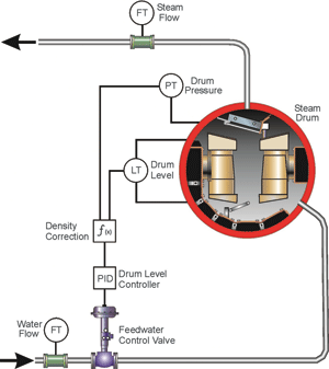
The single element control loop is indicated in Figure 1. The steam drum level signal is used as the process variable and the output of the controller is used to control the feed water flow to the steam drum. The set-point of the controller is configured to 50% of the drum level capacity. The steam drum pressure is used for density correction for the drum level measurement.
A standard open loop step change was used to analyse the process response. The control loop was placed in manual and the feed water valve was opened with a step change. The test data was analysed and the fast proportional and integral settings were selected from the program for the control loop.
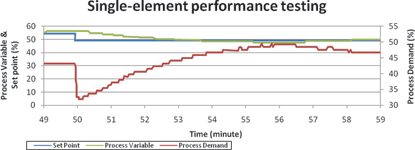
To test the tuning values the controller was placed in automatic and a step change was induced on the set-point signal. The test results shown in Figure 2 indicate that the fast tuning settings were optimal for the controller. The single-element was installed on boiler 1 as the base line.
Two element control
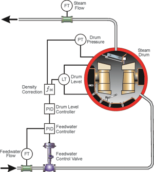
The standard two element controller is shown in Figure 3 and includes a feed water controller in cascade to the drum level controller. The drum level controller output is the feed water controller set-point. The feed water flow into the steam drum is the process variable for the secondary control loop.
Tuning optimisation started with the secondary (feed water control) loop. A step change was induced on the feed water valve and the feed water flow recorded. From the results, the data was analysed and the fast proportional and integral setting selected for the flow loop.
After the tuning parameters were obtained the flow controller was updated with the new values and the tuning was done on the primary (level control) loop. The primary loop had to be retuned due to the addition of the cascade flow control. The flow loop was set to automatic and the drum level loop to manual. A step change was introduced to the output of the drum level controller and the drum level recorded. The data was re-analysed and the tuning values were updated with new proportional and integral settings.
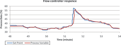
The two element control was then placed in operation and exceptional control was achieved as can be seen in Figure 4.
Performance testing
After the two element control was made operational on boiler 2, a load change was recorded on the boilers when the common turbine, supplied by the two boilers, tripped. The trip was caused by a turbine fault, thus the boilers did not trip and remained in service.
During a turbine trip, the steam supply valve is closed and the turbine by-pass line is opened. The turbine supply valve closes quicker than the by-pass valve can open, thus during the changeover steam flow is stopped momentarily. The turbine trip caused an upset in the boiler steam drum levels as indicated in Figure 5.
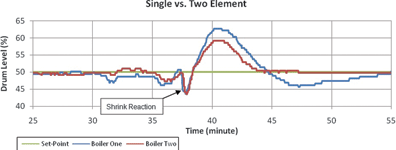
The reaction of the boilers proved that the two element configuration is faster than single element. Table 1 summarises the reaction of both boilers.
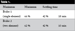
Comparing the two reactions shows the low level points to be identical, but there are notable differences in the maximum levels and settling times. The two element control on boiler 2 stabilised 8 minutes before the single element control on boiler 1. The load change confirmed that the two element control configuration reduces the settling time and reaction magnitude over single element configuration.
Conclusion
The two-element control configuration is a simple and effective method for control of steam drum level and with correct configuration and tuning, the drum level can be controlled within operating boundaries.
Normally, feed water flow is measured as part of the boiler process in any case. Thus, without major physical changes or financial expense, single element control can be upgraded to two element control. The two element system retains and stabilises the process more efficiently, with the only changes required being within the boiler control PID block.
In the next edition of SA Instrumentation & Control the three element configuration will be explained and tested.

Michael Brown is a specialist in control loop optimisation, with many years of experience in process control instrumentation. His main activities are consulting, and teaching practical control loop analysis and optimisation. He gives training courses which can be held in clients’ plants, where students can have the added benefit of practising on live loops. His work takes him to plants all over South Africa, and also to other countries. He can be contacted at Michael Brown Control Engineering, +27(0)11 486 0567, [email protected], www.controlloop.co.za
| Email: | [email protected] |
| www: | www.controlloop.co.za |
| Articles: | More information and articles about Michael Brown Control Engineering |


© Technews Publishing (Pty) Ltd | All Rights Reserved
 printer friendly version