

The problem
I was recently commissioned to investigate a heating problem by a client who tests ore samples by heating them to various temperatures. The heating rate is defined by either step changes or ramps in the setpoint, depending on the particular type of test being performed, all of which must comply with special standards.
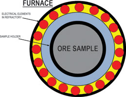
The samples are heated in a special holder mounted in the centre of a circular furnace which contains large electrical resistive elements mounted in refractory holders around the circumference. A drawing of the cross section of the furnace and sample holder is shown in Figure 1. The main problem was that fairly large overshoots in temperature past setpoint were being experienced.
Process dynamics background
Temperature processes that involve heating relatively large masses of substances fall into the integrating process class. These types of processes have to be controlled by balancing the input and output in order to keep the controlled variable constant. The most common example of an integrating process is level control, where the level will only remain constant if the inflow and outflow of the vessel are equal. In the case of an integrating temperature process, the heat entering must equal the heat leaving if the process temperature is to be constant.
A further complication in the control of integrating processes is that if the I (integrating term) is used in the controller, then there will be overshoots on setpoint changes. This is due to the rather strange phasing relationship between the input and output of an integrating process which starts off 90° out of phase, as opposed to a self-regulating process like a flow control which starts off in-phase.
In the initial meeting with the client it was believed that the heat loss from the furnace was very small. This would then place the process in a particular ‘class’ of integrating process commonly referred to as ‘batch reactors’ or ‘end point control systems’. They are unusual because of the very small heat loss, which in many cases can be considered as zero in the short term. Therefore, in these processes the temperature can only really be constant when there is no more heat entering the process. It is said that ‘the balance point is zero’, which means that the PD (controller output) is at 0%.
Another dynamic characteristic commonly encountered when heating relatively large masses of materials is that when a step change of heat is made on the input of the process, the temperature does not initially rise in a constant ramp which is characteristic of pure integrating processes, but it starts off with a relatively large lag which can be physically observed as a slow ‘curve-up’ into the ramp. This particular dynamic immediately indicates that the D (derivative) term should be used in the controller, as this is one of the only two cases of dynamics where the D term actually improves response. In this case of a slow integrating process with a long lag it can offer particularly dramatic improvement, as the D term if set equal to the lag will mathematically cancel it and this can result in a response to setpoint almost four times faster than that which would be achieved without the D term. A good example of this is a case of batch reactors being used in a pharmaceutical plant in the UK where they were not using the D term. Once it was shown how effective it could be, annual production increased by a whopping £14 000 000!
Controller testing
The control system was configured in a well known European make of PLC, the block that had been used being a dedicated temperature control block that allowed a special control zone which can be very useful for batch reactor temperature control.
I always test control blocks that have been configured in PLCs, as very few people ever set them up correctly. In fact, at least 85% of the time, I find them working incorrectly. Generally the main problems are incorrect triggering of the block so that the scan rate is wrong, which results in erroneous I & D timing, and secondly, incorrect PV and SP scaling which causes the wrong P gain. The test used to check controller operation involves fixing the PV at constant value and then making a step change in SP. This results in a constant step change in error and the response in the controller output allows one to measure and check if it is operating correctly.
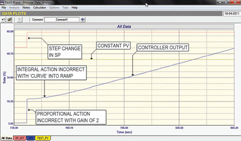
In this particular case the programmer had got the PV and SP scaling wrong and there was an additional problem as the integral term did not operate correctly, which also seemed to affect the P value. The test is shown in Figure 2. The P step is wrong, being too small for the gain in the controller and the I term does not ramp at a constant rate. It appears to have an initial lag on it as it ‘curves’ up into the ramp. This would appear to be a fault in the manufacturer’s software in the block.
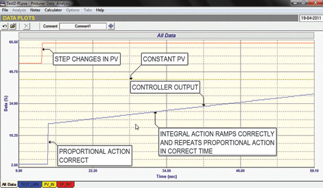
It then became necessary to change the block to a more commonly used one also provided as standard in the PLC – which I have used in countless previous applications and know works well. The successful test using this is shown in Figure 3. The P gain is correct and the I term is ramping at a constant slope and repeating the P action in the correct time.
Tests performed on the process
Various open loop tests were performed by manually stepping the PD (controller output). One of these tests can be seen in Figure 4.
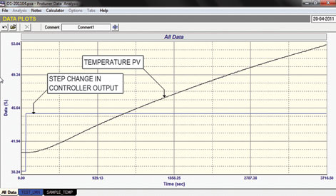
These tests showed:
1. There was indeed a huge lag of close on 200 seconds on initial heating of the sample.
2. As mentioned earlier it was initially assumed that the process dynamics would be the typical batch reactor type with virtually zero heat loss and with a balance point close to zero. The tests showed this is far from the case and that there is a great deal of heat loss. This can be seen clearly from the ramp rate of the PV which falls off as the temperature rises. This is because there is considerable heat loss from the furnace and heat loss is generally not linear, but more of a ‘square’ function as the temperature rises. Closed loop tests performed later showed that the average balance point (PD at balance) was close to 50%, which confirmed how much heat is being lost from the furnace! This makes it a very different type of control dynamic from a pure batch reactor.
3. The process (transfer function) is not linear and varies as the temperature changes. This means that control response will vary if the same tuning is used over the whole range and it may necessitate adaptive tuning. (Various tunings at different temperatures). Unfortunately there was insufficient time to perform all of the tests required to fully check this.
4. Another surprising finding was that the process dynamics were very different when cooling (ie with the elements switched off) to the dynamics when heating. On cooling there is an initial lead with a sharp drop in temperature followed by a slow decaying ramp. This actually means that when controlling with falling temperature (as when the PV is above SP), one may also need to use different tuning parameters for optimum response.
Conclusions
Unfortunately, due to the nature of the process dynamics and the fact that the client wished to perform tests with various sample masses and heating to different temperatures, it was absolutely necessary to use the I term in the controller, therefore overshoot could not be eliminated. The client wanted to avoid overshoots of more than 5°C, however, with the operating range of 0–1194°C, in percentage terms 5° is only 0,4% and in control reality this is tiny. On integrating processes when one uses the I term, it is normal to expect typical overshoots of about 2% on SP step changes on integrating processes – in this case about 24°C!
To try and limit the overshoot and speed up response to setpoint changes, a special control configuration was introduced whereby the output of the controller is switched to maximum when the PV is below 15% of the range from setpoint. As soon as the PV moves above the 15% limit the PD is cut back to 50% and full P+I+D control is initiated.
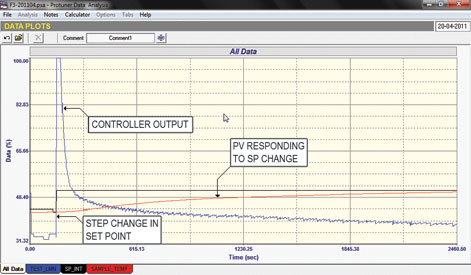
This worked very well as far as normal control is concerned. A tuning of: P = 7, I = 1000 s, D = 200 s, and D-lag = 20 s was used. An overshoot of about 10°C (0,8%) resulted, which I believe is very reasonable under the circumstances. Part of a final closed loop test with these settings is shown in Figure 5.
If one wanted better control, a possibility that might give better dynamics is to heat the sample holder by direct gas flame in the open (ie not in a surrounding oven), so that faster response dynamics be obtained. The faster the dynamics, the faster the control should be.

Michael Brown is a specialist in control loop optimisation, with many years of experience in process control instrumentation. His main activities are consulting, and teaching practical control loop analysis and optimisation. He gives training courses which can be held in clients’ plants, where students can have the added benefit of practising on live loops. His work takes him to plants all over South Africa, and also to other countries. He can be contacted at Michael Brown Control Engineering, +27(0)11 486 0567, [email protected], www.controlloop.co.za
| Email: | [email protected] |
| www: | www.controlloop.co.za |
| Articles: | More information and articles about Michael Brown Control Engineering |


© Technews Publishing (Pty) Ltd | All Rights Reserved
 printer friendly version