

During the latter part of 2002, Ana-Digi Systems was approached by DPI Plastics to quote on upgrading the additive dosing and mixing plant at its Roodekop factory. Having successfully automated the DPI plant in Cape Town in 1997, Ana-Digi Systems could carry much of the expertise and experience learned into the plant at Roodekop.
Overview of plant operation
Raw extrusion PVC material (corvic) is blown from the two storage silos into holding bins on the fourth floor of the mixing plant. This is the main component used for extruding pipe. If the recipe calls for injection moulding corvic, this is manually debagged at the debagging stations and blown up to holding bins on the fourth floor of the mixing plant. This is the main component used in the injection moulding plant.
Additives are blended with the corvic materials to create a particular recipe formulation. Corvic is weighed off in either one of two scales (W1 or W2) on the second floor (depending on which mixer is calling for product). At the same time, additives are being weighed on the scale on the third floor. When both sets of components are finished, the corvic and additives are dropped into a holding bin (one per mixer) where final waxes and pigments are added. These components are weighed manually and added manually if required. If the recipe calls for these components, the system waits for confirmation from the second floor before dumping into either mixer 1 or 2.
Once mixed to a preset temperature, each mixer dumps into its own cooler-mixer, where the product is cooled before being dumped into a low-pressure vessel below the coolers. Once the low-pressure vessel is full, the finished product is blown via an interlocked coupling station to either one of 13 finished-product silos for extrusion or one of four injection-moulding silos. Recipes which are for special orders or experimental are dumped out of the low-pressure vessels into bulk bags.
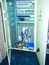
The operators control the whole plant from the control room (first floor) where all plant status values are displayed on their computer screen. The control room also houses the main control PLC and the two mixer control panels.
The Roodekop plastics additive handling and mixing plant is mounted on five floor levels and has two external debagging stations. Two external 75-ton silos store and supply the raw PVC material, which is blown to holding hoppers on the fourth floor. Products are weighed off according to recipe formulations and mixed in three combination mixer-coolers. Once it is sufficiently cooled, the product is blown to one of 17 finished product silos.
The upgrade
An initial site inspection was done in order to inspect the site, gauge the magnitude of the project and gather information regarding the customer's requirements. A further site inspection was done towards the end of November 2002, when photographs were taken of the existing installation to assist with planning of the new strategy.
Basic information relating to cable lengths and routing, operating voltages of solenoids, motor sizes, input/output points and functionality, etc, was gleaned from the plant. Old circuit diagrams, although rudimentary, were also collected to further assist with assessing the system requirements and functionality. A meeting with all responsible parties was convened to establish the customer's requirements for the new system.
Armed with this information, detailed lists were drawn up of physical inputs and outputs of the existing plant as well as future proposed developments. Allowances were also made to accommodate frequency inverters for dosing screws, new weight indicators for PVC and additive scales, and new operator panels for the two mixers and cooler-mixers. As weighing accuracy was critical, careful consideration had to be given to cable routing and screening, as well as correct earthing practices, in order to avoid interference from frequency inverters and earth loops. The mixer-cooler panels would also be upgraded with new soft-starters, switchgear and operator panels.
An LG GM4 rack-mounted PLC was chosen as the master-controlling element in the system. Ease of programming, large on-board memory, range of modules and flexibility favoured the GM4. As the equipment was located on five different floors, it was decided to utilise the LG F-Net bus system (based on Foundation Fieldbus), because of its economical pricing, high speed, flexibility and reliability. This configuration made distributed I/O the natural choice for the control of the four additive handling floors and the remote coupling station on the ground floor. The GM4 would serve as the master controlling element in the system.
The remote stations would consist of three LG GM6 PLCs. These rack-mounted PLCs were selected for their cost effectiveness, expandability and wide range of I/O cards. Remote bus (RBEA) interface cards replace the CPU cards on these racks to cater for F-Net. This effectively made the remote PLCs an integral part of the master.
LG GM7 PLCs would cater for the requirements of the two mixer panels. These could be intelligent standalone PLCS, but would still be 'transparent' as remote I/O, effectively working in master/master mode.
The four additive handling floors were divided into two, one remote cabinet on the third floor (handling the requirements of the third and fourth floors) and one remote cabinet on the second floor (handling the requirements of the first and second floors). A third remote cabinet was placed at the coupling station to accommodate the large number of pipe coding inputs and an off-spec product hopper.
The only inter-wiring between the control room and the three remote PLC cabinets would consist of a single comms cable and three power cables. It was decided to leave the five blowers hard-wired, due to the size of their motors (18 to 30 kW) and their proximity to the control room. Nevertheless, the cabling for the blowers was reduced to one supply cable and an I/O cable. Effectively, the huge quantity of cable used to hard-wire the original system would be removed, the overall wiring requirement of the new system being reduced by approximately 70%. The competitive pricing of LG PLCs and the huge reduction in overall wiring costs and racking meant that these savings in system costs could be passed on to the customer.
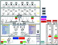
A Pentium 4 PC, with 19" screen, running LG GLOFA software and a 1500 I/O Adroit open automation technology scada package, would cater for PLC programming, plant graphics, reporting and operator input.
During April 2003, Ana-Digi Systems was awarded the contract to upgrade the plant. It immediately set about engineering the panel designs, technical drawings, cabling schedules and wiring diagrams. LM Technical Services was sub-contracted to build the panels according to wiring diagrams supplied by Ana-Digi. The provision to use new cable trays, rewire the plant and remove redundant old cables and racking was included in the contract. Cable schedules for the new cabling were drawn up and approved by Ana-Digi.
One major requirement of DPI Plastics was that downtime be kept to a minimum. This meant that all wiring had to be parallel wired, but not connected. The plant was live and had to be kept operational at all times. In many cases, the huge quantities of old cables interfered with the path of the new ones, necessitating a different routing for the new cable trays.
Shutdown of the plant on stock-take weekends (usually the last weekend of each month) afforded Ana-Digi the opportunity to tackle the first phase of the changeover at the end of August 2003. Because the commencement date had been brought forward at short notice, Ana-Digi was not 100% prepared for the cut-over, but all parties agreed that it would be better to make a start, rather than to wait another month.
The fact that one of the mixers would be running that weekend complicated matters, as the plant could not be fully isolated and switched off and all cabling had to be treated as live. Additionally, this meant that old cables could not be cut for removal as originally planned. Careful checks had to be made to ensure that interlocking was not affected and live cables were marked before any work could commence. This hindered progress for the whole weekend as everything had to be double-checked before being disconnected. Individual live ends had to be carefully disconnected and taped up before tackling the next connection. A further complication arose because of inaccuracies in the original documentation and circuit diagrams.
Because of the large number of disconnections/connections that had to be made to motors, switches, solenoids, etc, in the short time available, the Monday morning start-up was delayed. Motor directions were checked and corrected where required. All input and output functions had to be confirmed on all the floors. Comms on the bus system had to be established, scales had to be calibrated and values verified in the PLC.
By Tuesday morning, one mixer was running. Dosing screws, utilising LG frequency inverters, had to be adjusted to accommodate fast, flow and incremental speed ranges. This had to be done in order to suit the fluidity of each component.
As the heart of the old system had literally been removed, lost interlocking between the old and new control panels and the third mixer system had to be re-established. This was an unfortunate spin-off from not being fully prepared, due to the early, unscheduled start to the system cut-over.
While Ana-Digi Systems addressed the interlocking, PLC and scada issues, LM Technical looked after the racking, wiring and cabling. By the end of the week, both mixers were running (still from their old panels) and the scada system was enhanced to ease operation. This enabled some of the production backlog to be caught up and the system operation to be streamlined.
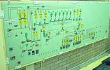
The control room was looking rather untidy at this stage, with interface cables lying on the floor, linking old and new systems. This meant that the old mimic panel, which was the main panel that we were aiming to remove, would remain a stumbling block a bit longer. Because nearly all the external interlocking went through this panel, it had to remain operational until phase 2, which began at the end of September.
This time, Ana-Digi was prepared for the conversion and start-up on the Monday went smoothly. There were few problems and these were quickly addressed. This afforded Ana-Digi the opportunity to remove the bulk of the remaining old cables. All in all, some five pallets of stacked armoured cables were removed, allowing for the system to be neatened up. At this point, the SI had gained control of 70% of the plant, including all the silos and blowers.
Phase 3 incorporated the two debagging stations and saw the replacement of the two old mixer panels. Each mixer had its own intelligent LG GM7 PLC linked to the master LG GM4 PLC. A 160 kW Elonics soft starter for each mixer was also incorporated to ensure smooth run up. Scada screens were written to duplicate the operation of the external operator panels. This gave the operator full control from his armchair.
Off with the old...
Once 100% control of the plant was attained, the huge mimic panel, which had dominated the control room for years, was removed and cut up with an angle grinder. The hole in the control room floor was welded closed and the old 'mimic' was mounted on the wall for posterity, a reminder of a bygone dinosaur.
Problems encountered have not been glossed over, as the above description represents a real-world rework of a major system, where production has to continue and available time is limited.
While the pressures of production often clash with the ideal world system changeover, it is clear that with perseverance and mutual client/contractor co-operation, compromises can be achieved, to the mutual benefit of both parties.
The flexibility of the system now allows DPI Plastics to effectively meet production deadlines and to easily experiment with new recipes.
DPI Plastics
The DPI plant in Roodekop manufactures plastic and polyethylene piping of all descriptions. From large bore water pipes and sewerage pipes to polyethylene irrigation piping and flexible PVC reinforced hose, all industrial and domestic pipe requirements are catered for. The injection moulding division manufactures fittings and components for gutters and drain pipes.
Because of this diversity, the quality of the finished product can only be as good as the quality of the raw materials from which it originated. The additive and main component dosing and weighing and the mixing process is of utmost importance. DPI Plastics is well aware how crucial these elements are to their process. The old mixing plant, which had been in existence for more than 20 years, was not capable of carrying the demands for new products and quality into the future. The time had come for an upgrade to the mixing plant, which was duly completed by Ana-Digi Systems in November 2003.
For more information contact Ana-Digi Systems, 021 914 9030, [email protected], www.anadigi.co.za


© Technews Publishing (Pty) Ltd | All Rights Reserved
 printer friendly version