A high-pressure steam flow control in a reboiler on a column in a petrochemical refinery continually cycled when placed in automatic. Several attempts had been made to tune the controller, but these were unsuccessful. The operators had to control the flow manually, but had great difficulty in getting it to the desired flow value.
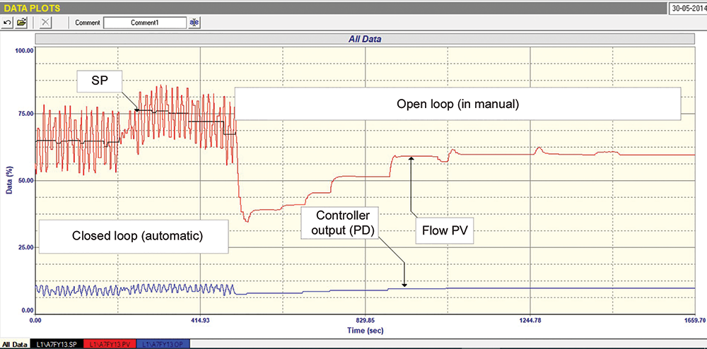
Some open and closed loop tests were performed on the flow, and they revealed some remarkable things. Figure 1 is a test, with the controller firstly being set in automatic (closed loop testing), with the ‘as-found’ tuning parameters in the controller, and a few small set point (SP) steps being made. Once that was done the controller was placed in manual (open loop testing) and some steps were made on the controller output (PD).
Observations made from the closed loop section of the test
• The loop was in a continuous cycle, which appeared to be caused by bad tuning. Although it is hard to see in the test due to the aliasing of the signals, caused by a relatively slow scan rate in the OPC data interchange system used to pick up the signals from the DCS, this could be confirmed by running a frequency analysis on the PV signal. This revealed that the period of the dominant frequency in the cycle was approximately 13 seconds. This is typical of the frequency of cycling caused by instability due to bad tuning for a flow loop. As a general note, such cycling generally occurs at a frequency close to the ultimate (or natural resonant) frequency of a closed loop flow control loop.
• The amplitude of the cycle on the PD was very much smaller than that of the process variable (PV). This would indicate a process gain much greater than unity. Process gain is the ratio of the change in PV over the change in PD. This would indicate a largely oversized valve.
• This is also confirmed by the fact that the average value of the PD in the cycle was around 7%, which assuming that the transmitter and valve calibrations were correct, meant that the valve was working far too close to seat. A well-established rule of thumb for most types of pneumatically operated valves is that under normal control conditions they should operate at or above 20% opening. There are two reasons why valves should not work close to the seat. Firstly, they may encounter excessive differential pressure, with which their actuators cannot cope; secondly, the manufacturers find it very difficult to machine the valve seats and/or plugs so that the correct inherent flow characteristics can be maintained, so installed nonlinear characteristics may be encountered at low flows.
Observations made from the open loop section of the test
• The installed characteristics of the valve are nonlinear, which is shown by several small equal steps in the PD being made, and the magnitude of PV increasing with each subsequent step.
• The PV jumps around at times when the PD is steady, which would indicate a possible slight play in the linkages between actuator and actual valve.
• The total change in the PV is about 10 times greater than that of the PV, which would indicate that the valve is possibly about 10 times oversized, confirming the observation made above in the closed loop section of the test.
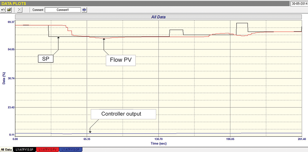
Figure 2 shows a section of an open loop test made with a step made on the PD. The purpose was to try and establish tuning values that could possibly work. It is of interest that, in this step, the process gain was calculated to be a massive 34.
A closed loop test using the new tuning is shown in Figure 3. Interestingly, some sort of poor closed loop control was actually now being achieved. However, it can be seen that the PV again suddenly moved by itself at one point, probably due to play in linkages. It also showed that the PV apparently did not move properly on two of the SP step changes, and also apparently exhibited a lot of dead time as seen on the first large SP change downwards.
However, one must be reasonable. To get the PV to move, the PD has to move only a tiny amount, and this must be done quite slowly to avoid instability. The valve was actually doing quite a remarkable job, but it is absolutely ridiculous to try and get good control with such a massively oversized valve. There was no doubt that the valve needed replacing with a smaller one.
For the record, the original tuning was
About Michael Brown
 Michael Brown
Michael Brown is a specialist in control loop optimisation, with many years of experience in process control instrumentation. His main activities are consulting and teaching practical control loop analysis and optimisation. He now presents courses and performs optimisation over the internet. His work has taken him to plants all over South Africa and also to other countries. He can be contacted at: Michael Brown Control Engineering CC, +27 82 440 7790
| Email: | [email protected] |
| www: | www.controlloop.co.za |
| Articles: | More information and articles about Michael Brown Control Engineering |


© Technews Publishing (Pty) Ltd | All Rights Reserved
 printer friendly version