As mentioned many times in my articles, the widely held belief in many plants that tuning will solve all base layer control problems is completely fallacious. Bad tuning is generally not the main reason for loops to perform badly, or not at all. This is usually due to some sort of problem in the various elements of the loop, or in the design or the control strategy.
The elements of the control loop consist of:
• The process itself.
• The transmitter.
• The controller.
• The final control element, which in most cases consists of a valve, an actuator, a positioner and a current to pneumatic (I/P) converter.
In general, about 80% of all problems are due to faults in the final control element. However, the other elements in the loop can have problems, so it is important when performing optimisation that all these various elements, in addition to the control strategy, are investigated before even thinking of tuning.
The example given in this article is of a very important level control in a distillation column in a large petrochemical refinery. The control requirement was that the level should remain as constant as possible at setpoint in the face of frequent load disturbances. A large number of downstream processes were adversely affected if the level varied. The operators reported that the control was not performing properly, and large variances in level were being experienced when the control was in automatic. The control seemed to work at differing speeds, sometimes responding very quickly with cycling, and sometimes extremely slowly. They had resorted to trying to control it in manual, with little success.
The plant’s C&I; personnel had been called on and had spent a long and fruitless period trying to retune the control, with no improvement at all. Level controls normally fall into the class of processes known as integrating or ramping, as opposed to the other class of processes known as self-regulating or self-balancing. This is typified by flow control, where a step change in the process demand output (PD) when in manual results in the process variable (PV) changing and then settling out again. The PV basically follows the movement of the PD.
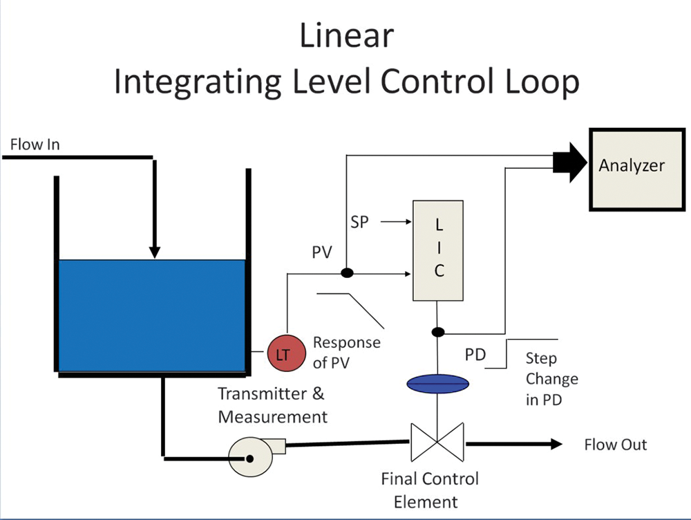
An integrating process is one where one has to balance the input and output of the process to keep the PV constant. This is best illustrated in Figure 1, where we can see a level control on a tank. If the controller is in manual, the level will only be constant if the input flow equals the output flow. This is known as a balanced process, and the PD value at this balance is called the balance point. If the operator makes a step increase on the PD, the output flow will now be bigger than the input flow, and the level will start moving down in a perfect ramp. If no further action is taken by the operator, the tank will eventually run empty. However, if the operator restores the PD to the balance point value, the in and out flows will again be equal and the level will remain constant, albeit at a lower level in the tank.
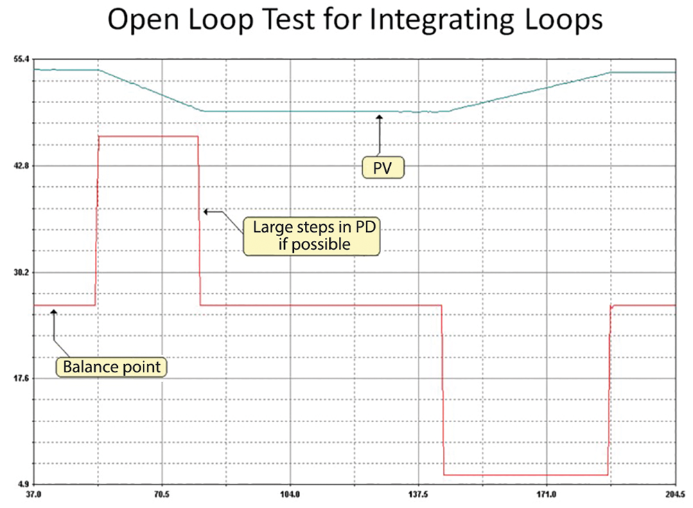
If a step change were to be made on the PD in the opposite direction to close the valve slightly, the inflow would be greater than the outflow, and the level would start ramping upwards. This would continue until the PD was restored to the balance point. These movements are shown in Figure 2.
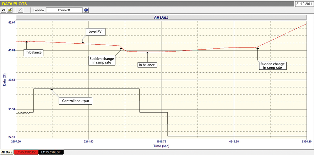
In the example of the level control in the distillation column, a similar open loop test was performed and this is shown in Figure 3. It can be seen that when a 5% step change was made on the PD to open the valve slightly, the level started moving down in a constant ramp. It continued moving down until it reached 47%, and then the ramp rate suddenly and dramatically increased until the level reached 45,5%. At this point the ramp rate slowed down to the original rate. The PD was put back to the balance point shortly after this and the level then remained constant.
A little later the PD was stepped down by 5%, and the level started ramping up at a rate very close to the slow ramp rate that occurred on the previous step. After the level had moved up a little, the ramp rate suddenly slowed, and for about five minutes the level appeared to remain constant, but then suddenly started moving up very quickly at quite a high ramp rate.
What could cause this to happen? The first thing that one would suspect would be a sticky valve that suddenly jumps. Secondly, one could ask if the vessel is uniform in shape. Thirdly, is there a problem with the transmitter? As mentioned earlier, most faults are caused by problems in the final control element. It is often very difficult to determine such faults on an integrating process where changes on the PD from the balance point result in ramps. It is much easier to find such faults on self-regulating processes where the PV basically follows movements of the PD.
In this particular case the level control was the cascade master to a secondary flow cascade loop, and this was tested separately and found to be working well. The vessel was uniform in shape, so that left the level transmitter as the probable cause of the problem. Now I have found that plant personnel seldom seem to think that the transmitters they are using can cause problems. This belief has become even more widespread nowadays, when computer technology is embedded into what are called ‘smart’ transmitters. I often ask the plant C&I; people I am working with about the details of the transmitters used on certain processes, and have seldom found that they even know what type of transmitter it is, and what its capabilities are.
Over the years, I have found that transmitters are the cause of faulty control in quite a few cases. In this case, when we managed to get details on the transmitter, we found that it was a float type device, with a float that rests on top of the liquid, and slides up and down over a tube as the level varies. The transmitter has a sensor in the tube measuring the position of the float. It was pretty obvious that the float was not sliding freely up and down the tube, and was sticking a bit at times.
Now, the methodology of tuning an integrating process incorporates what is known as the process gain of the level process. Very roughly this is actually the slope of the fastest ramp that can be obtained on that particular process. What was happening was that the tuning, which had been calculated from the slow sticky ramp rate, was wrong when the float moved freely. This was the main cause of the instability when the control was in automatic.
When one discovers the cause of a problem like this it seems so simple, but the fact is that many people working on base layer controls don’t analyse the basics properly. They waste many hours, if not days, trying to fix problems with a ‘magic’ tune. Incidentally, the majority of people do not use scientific tuning, and rather set the parameters by trial and error. This seldom gives good tuning.

Michael Brown is a specialist in control loop optimisation, with many years of experience in process control instrumentation. His main activities are consulting and teaching practical control loop analysis and optimisation. He now presents courses and performs optimisation over the internet. His work has taken him to plants all over South Africa and also to other countries. He can be contacted at: Michael Brown Control Engineering CC,
| Email: | [email protected] |
| www: | www.controlloop.co.za |
| Articles: | More information and articles about Michael Brown Control Engineering |


© Technews Publishing (Pty) Ltd | All Rights Reserved
 printer friendly version