

One of the biggest problems associated with the final control element is hysteresis and backlash. This can be roughly defined as the maximum difference obtained in stem position for the same input up-scale and down-scale. A test to measure hysteresis and deadband in a self-regulating loop is illustrated in Figure 1.
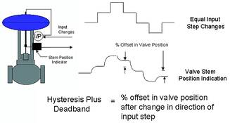
Normal hysteresis
Hysteresis is normally caused by the force that appears every time the valve stem is going to be reversed, ie moved in a direction opposite to the previous direction of movement. Valve experts have described static frictional force as the amount of force needed to bend the end-fibres of the packing material in contact with the valve stem in the new direction of motion. Once the static frictional force has been overcome by energy provided by the motive power of the actuator and the stem actually starts moving, the static friction force disappears and is replaced by a sliding frictional force which is very much less than the original static friction.
Subsequent equal movements of the valve stem in the same direction will then generally be greater as the static friction has now disappeared, and all the energy produced in the actuator now goes directly into moving the valve stem. It only reappears again on the next valve reversal. Any deadband (mechanical play or backlash) in the mechanisms of the valve, actuator and positioner combination, adds to the hysteresis effect when reversing the valve.
As a rough rule of thumb based on tests performed on many thousands of valves, a hysteresis value of not more than 1% of valve movement span is acceptable in practice for a pneumatically operated valve fitted with a positioner. This figure increases to 3% if there is no positioner on the valve.
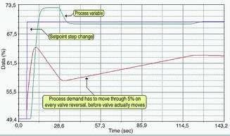
Hysteresis and deadband increase control variance. In the case of self regulating processes they increase the time that the controller needs to make corrections for a load disturbance or setpoint change, because every time the controller has to reverse the valve, the controller has to move the PD (controller output), through the full hysteresis range before the valve will move in the opposite direction. As this movement of the PD is performed at the integral term ramp rate, which gets less and hence slower, the closer the PV gets to setpoint, it can take a very long time for the process to finally actually settle out at setpoint.
Figure 2 illustrates this effect on a flow loop with 5% valve hysteresis, responding to a step change in setpoint. The process has taken close on 3 minutes to settle at the new setpoint. If the valve had been hysteresis free, the process would have settled out at the new setpoint in approximately 20 seconds. It should be noted that hysteresis and deadband do not cause continuous cycling on self-regulating loops.
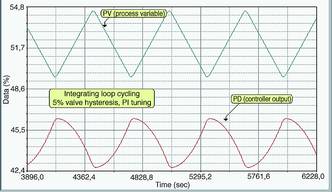
Integrating loops on the other hand always cycle if there is any hysteresis and deadband in the valve, and if the 'I' term is used in the controller. This is illustrated in Figure 3. Thus it is very important that valves used on integrating processes are in good working order, if cycling and increased control variance are to be avoided!
Negative hysteresis
On reversing a valve with normal hysteresis and deadband using equal steps of PD and as was seen in Figure 1, the valve stem does not get back as far as the equivalent position where it was on the step before the reversal. However, on certain loops one finds that the stem actually overshoots this position on the return. This is illustrated in Figure 4.
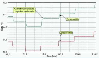
We have named this particular phenomenon 'negative hysteresis'. It occurs if a positioner is present and it is a sign of an 'under-powered' actuator that has difficulty in overcoming the static frictional force. (It may be too small or else the packing glands have been over-tightened.) The reason for the overshoot is that the positioner seeing the valve is not moving, starts inputting excessive pressure into the actuator. Eventually there is enough pressure in the actuator to overcome the static friction. However, as the static frictional force disappears, the excess energy in the actuator pushes the stem too far.
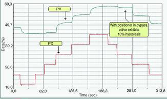
If it were possible to bypass the positioner and allow the incoming air signal to operate the actuator directly (but be careful that the actuator bench set is in fact 20 to 100 kPa) and then repeat the step test, one would see that the valve now exhibits high normal hysteresis. Figure 5 illustrates such a test carried out on the same valve that showed the negative hysteresis in Figure 4. The normal hysteresis of approximately 10% is unacceptably high.
Negative hysteresis is most undesirable. For good control it is essential that the actuator should have sufficient power to move the valve to any desired position. Loops with valves displaying negative hysteresis tend to be very cyclic in closed loop control. On occasions I have seen loops displaying this phenomenon going completely and wildly unstable intermittently, and others cycling continuously.
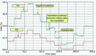
On some occasions, the positioners on valves with negative hysteresis manage to correct the overshoot after a while and bring the valve stem back to the correct position. However this may not happen on every occasion, and it makes the valve dynamics very nonrepeatable. Such behaviour is illustrated in Figure 6. This open loop test was performed on a flow loop in a brewery using a 'home-made' oversized butterfly valve, assembled from components purchased from different manufacturers. It can be seen how nonrepeatable the responses are.
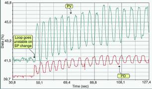
A closed loop test shown in Figure 7 illustrating the instability resulting when the controller was put into automatic and a setpoint change made. It is not a good idea in general for a plant to try and save money by making up its own valves - if they want reasonable control.
| Email: | [email protected] |
| www: | www.controlloop.co.za |
| Articles: | More information and articles about Michael Brown Control Engineering |


© Technews Publishing (Pty) Ltd | All Rights Reserved
 printer friendly version