

During a recent control course presented in a South African continuous process plant, part of the practical work was spent in optimising a hydrogen/nitrogen gas mixing system
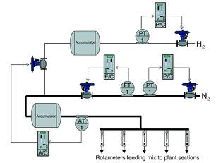
A schematic of the mixing system is shown in Figure 1. The hydrogen and nitrogen are to be combined in an approximate ratio of 1:10. Hydrogen is fed into an accumulator via a pressure reducing control system. The nitrogen also passes though a pressure reducing control system, but immediately after that it is passed through a flow control system, and from there into an accumulator.
A strategy of passing fluids firstly through a pressure control system and then immediately into a flow control is something that one finds in many plants, and it certainly never ceases to amaze me, because it cannot work. Firstly, close coupled pressure and flow controls are highly interactive, and secondly they are trying to defy the natural gas laws. Obviously you can only control either the pressure or the flow.
Movement of either of the valves is going to upset the other control. In general, for this strategy to work, one must have a large capacity of gas between the pressure and flow valves. For example if they had put the flow controller downstream of the nitrogen/hydrogen mixture accumulator it might have worked, but as will be seen below this is also illogical because there was a manual control of flow further downstream.
The hydrogen was introduced into the nitrogen downstream from the flow control valve and before the mixture accumulator via a mixture control valve. An on-line hydrogen/nitrogen mixture analyser sampled the gas downstream from the mixture accumulator. Its signal was fed into a mixture controller, which controlled the amount of hydrogen flowing into the mixture. The gas was then fed into various points on the process via 'rotameters' (variable area flow meters) with integral manual regulating valves.
Plant operators experienced difficulty in setting up the flow through the individual rotameters, for as soon as they adjusted the flow in one - it upset the flows in the others.
The flow rates through the individual rotameters do need to be adjusted on a fairly regular basis depending on the product being manufactured in the plant at that time.
When one has to control a system like this, it is important to look firstly at the control requirements and then to try to satisfy these requirements keeping interaction to the minimum. The main requirements in this case are to introduce hydrogen and nitrogen into the process at the correct percentage mix, to allow the operators to set up the individual flows through the rotameters without them interfering with each other, and of course to keep these flow rates constant.
To satisfy the last two requirements it is necessary to keep the pressure in the header feeding the rotameters as constant as possible. Bearing in mind that the nitrogen flow is approximately ten times larger than that of the hydrogen, it becomes apparent that the control of the nitrogen pressure is far more important than nitrogen flow or hydrogen pressure. It was found on testing, that the nitrogen flow controller had been tuned fairly fast and the pressure controller detuned. The way the system had been set up with the nitrogen flow control as the fast loop was causing the interaction on the rotameters. As soon as the operators changed the flow on the one, the flow controller would then compensate by passing different rates through the other rotameters to keep the total flow constant.
The first important thing that had to be done to optimise the system is to take the nitrogen flow control out of the system. This was easily effected by setting the controller to manual mode. The output of this controller was gradually increased to a maximum to open the valve fully, and keep the pressure drop across it to a minimum. If one wants to keep the pressure on the rotameters' header constant, it is not good to have pressure drops upstream as they will vary with flow. (There is a possibility that the best place to situate the tap to the nitrogen pressure transmitter would in fact be downstream of the mixture accumulator, but it may also adversely increase interactive effects. Unfortunately it was not possible to experiment with this in the plant at the time).
Now the next thing was to determine the location and magnitude of interactive effects in the system. To do this one must use a multi-channel recorder and monitor all the inputs and outputs of the various processes that could interact. In this case six channels were required to record the input and outputs of the nitrogen pressure controller, the hydrogen pressure controller, and the mixture controller. All three controllers are then placed in manual, and step changes in the output of each are made sequentially to observe the effects on the inputs (process variables) of all three loops.
The results of these tests were that both the nitrogen and hydrogen pressures affected the mixture as could be expected. However, changes on the mixture controller affected the hydrogen pressure but had negligible effect on the nitrogen pressure.
Bearing these effects in mind, and also that load changes in the system would be negligible, then the tuning strategy would be to tune the nitrogen and hydrogen controllers as fast as possible and tune the mixture controller slowly to minimise its interaction with the hydrogen control.
Before starting the optimisation of the various individual loops, it is also essential that one fully understands all aspects of the controllers used and what options are available. Previous articles have dealt exhaustively with this important subject. In this case the plant is using sophisticated European-made multiloop standalone controllers. These controllers are extremely complex with a huge range of options and configurations.
Unfortunately, even though written in English, just like many other makes of controllers, the manuals are almost impossible to understand. How manufacturers of such sophisticated equipment ever expect their users to understand their controllers is beyond me. Even people with a great deal of knowledge of controllers are often unable to find their way through and understand the manuals. Very often the local agents also have very little knowledge, and frequently one has to phone the overseas manufacturer to find someone who can assist.
In this case it took several hours of searching through numerous volumes of a library of manuals on the controllers, before one could collate the more essential details required to understand the basic essentials of the controller's operation. Even after finding this information, it took several more hours to actually find out how and where to implement required changes in the controllers' software.
One point of interest is that the default configuration of the controller is set by the manufacturer so that only integral action results on set point change. The controller does however react to load changes with full P, I and D (if used) action. Now although there was in fact a paragraph on this subject in an obscure part of the manual, it does not say this is the default, and certainly no one has ever informed the plant I&C personnel about this fact. This is vital knowledge, because firstly, it is impossible to tune a controller properly with this setting, because every time one tries to test the response you only get I action. Secondly, even though a slow response to setpoint is often desirable to minimise bumping the process, there are processes that require a fast response when the operators make setpoint changes. It is essential when tuning controllers, and when judging control responses, that the controller be configured so that one can see the P and D (if used) actions, as well as the I action when responding to setpoint changes.
It is interesting to note that because of the default setting in the controllers, that not one loop in the whole plant using this controller could ever have been tuned properly - and that no one in the plant was aware of this. This is not only the case in this plant, but in nearly every other plant I have been in, using controllers with this configuration. This reflects badly on the education system of institutions teaching control, and also on controller manufacturers who cannot be bothered to point out a simple fact like this in their manuals, or to train people properly on the use of their controllers.
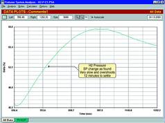
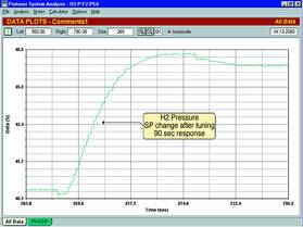
The hydrogen pressure control loop was optimised first. Although there was no noise on the process variable the transmitter had been configured with a five-second filter and the input on the controller with a one-second filter. These are completely unnecessary and will only affect the control adversely (see previous articles on filters). Figure 2 shows the response to a setpoint change with the original tuning and with the filters still in the system. The tuning had a proportional band of 200%, an integral of 1 minute/repeat, and a derivative of one second. The response with these settings was extremely slow with a big overshoot taking over 12 minutes to respond to a 10% setpoint change. With the new tuning, a proportional band of 35%, an integral of 3,75 minutes/repeat, and no filters, the response was improved to 90 seconds. This is shown in Figure 3.
The nitrogen pressure loop was then optimised. Its response after tuning was much improved, with a response time about ten times faster than the as-found tuning. The original response was also very slow and cyclic, taking a long time to stabilise.
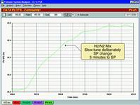
Finally, the hydrogen/nitrogen mixture control loop was optimised. As mentioned earlier this loop will interact with the hydrogen control. To decouple interactive loops by tuning, one must be tuned fast, and the other slow. In this case the hydrogen pressure was tuned fast, so it was necessary to keep the mixture control's tuning relatively slow.
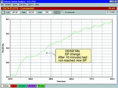
The original as-found tuning was terrible. After making a 5% setpoint change, the mixture had not even reached the new setpoint when the test was abandoned some 10 minutes later, see Figure 4. The response with the new tuning, which we consider slow, is shown in Figure 5. The response to the change was now completed in 3 minutes, and had little effect on the hydrogen pressure.
The mixture control is now running a lot better. There was however a lot of resistance on the part of the process operators to having the hydrogen flow controller out of the circuit. It is very important that the process people also be included in the decision making when optimising a system, and that the reason for changes be explained carefully.
Michael Brown Control Engineering
(011) 486 0567


© Technews Publishing (Pty) Ltd | All Rights Reserved
 printer friendly version