

One of the more difficult types of processes that I have been asked to optimise, is the level control of the mould in a continuous casting machine found in large steel manufacturing plants. A basic diagram of such a machine is shown in Figure 1.
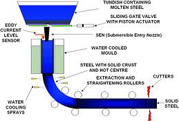
Molten steel is poured continuously through a water cooled mould from a tundish via a control `valve' to regulate the flow, and then through a ceramic submerged entry nozzle into the mould. The outside of the steel starts solidifying in the mould. Water sprays further cool the steel `strand' as it leaves the mould. As shown in the diagram the strand is curved via a series of rollers through 90° and emerges as a horizontal slab. As it leaves the machine at this point it is now solid, and is cut up by a flying cutter as it moves along.
It is interesting to note that their record of one continuous casting for one of the machines I worked on, is approximately 10 km for a strand with a cross-sectional area of 1600 x 250 mm. Also of interest is the fact that the mould width can be varied between 950 mm and 1800 mm.
Thus pretty large slabs of steel can be produced in these gigantic machines. The casting speed of the machine can also be varied. Obviously, the faster it can run, the higher the productivity of the process. The mould is also kept in a relatively slow vertical up and down oscillation to prevent the molten steel from sticking to the walls.
The actual behaviour and characteristics of the steel strand as it solidifies are not completely understood, but a metallurgist described the strand leaving the mould as similar to a colossal balloon filled with a liquid. The steel skin is still very elastic.
The whole control of the process is entirely dependent on keeping the level of the molten steel in the mould at a very constant level. Ideally the process metallurgists would like the level to be kept within ±1 mm. If the level fluctuates the quality of the steel is badly affected. Obviously high costs would be entailed if the steel overflows the mould, because it would entail repairs and would interrupt the process for many hours.
The mould level can be measured by nuclear technology employing a radioactive source on one side of the mould and a vertical 'strip' scintillation counter on the other side. Alternatively and more recently, an eddy current level monitor is used. Of the two I have found that the latter gives a 'cleaner' signal.
There are two common methods used to control the flow of steel into the mould. The first is to use a ceramic stopper rod pushing into a circular outlet (or hole) in the tundish. I have found this device particularly bad for several reasons. The tip of the stopper is constantly eroding and changing shape, which makes the installed valve characteristics variable and non-linear. Also on one machine I worked on, the flow varied between 0 and 100% over a movement of a couple of millimetres of the rod. This increased the process gain of an already fast integrating process (see later) dramatically, and necessitated in extremely small gains in the controller, which effectively necessitates a very slow tune.
The second method, which in my opinion is far superior, is to use a gate with a circular hole in it, sliding horizontally over an identical opening in the bottom of the tundish. This has relatively linear installed characteristics, does not cause an unnecessary increase in process gain, and allows for a much finer and faster control. The gate is moved by an extremely fast and accurately positioned hydraulic actuator.
There are some very interesting and difficult problems associated with the control of this process. Firstly, being a level, it is integrating. The next problem is that it is extremely fast which means it has a very high process gain. Typically I have measured a mould with a process gain of about 0,3, which is equivalent to a retention time of about 3,3 seconds. This is really fast. Fast integrating processes have to be tuned relatively slowly with a smaller gain in the controller for stability. This means that the control has to be relatively slow, and cannot react very quickly to fast changes. As will be seen in an article on tuning which will appear shortly in my Loop Signature series, the following relationship is approximately true for integrating processes:
PG x Kp x I = Constant
Where:
PG = Process gain
Kp = Controller gain
I = Controller integral in time/repeat for a series or ideal algorithm
The relevance of this is that if the process gain changes, then the tuning parameters have to be changed proportionally to keep the relationship in balance. Unfortunately there are many factors that can change the process gain and affect the control. These include:
* Mould width (ie, mould volume).
* The level of steel in the tundish will affect the flow into the mould.
* Steel grade.
* Casting speed.
* State of submerged entry nozzle which slowly blocks up over time, and has then to be replaced.
* The molten steel is not completely consistent. This can result in the flow into the mould varying quite suddenly.
Changes in any of these factors could mean that different tuning parameters may be needed to keep control optimum, (sometimes referred to as gain scheduling or adaptive tuning).
Report on the controls in a particular casting machine recently investigated
I thought it might be interesting to show some of the problems that were found.
The machine was quite a large one with four strands. It is controlled by a well-known make of American PLC, and the controls had originally been optimised by the original German consultants. The level measurement is the eddy current type, and the final control element is the sliding gate valve type described earlier.
The process operating personnel were not at all happy with the existing control of the level. It deviated a lot from setpoint, and could not cope with load changes. It was extremely bad on wide mould widths particularly at higher machine speeds.
The gate was first checked. It was found that it followed the output signal of the level controller quickly and accurately. It was one of the fastest and best final control elements I have ever encountered. The plant people had found and rectified an earlier problem with hysteresis caused by play in the coupling between the piston of the hydraulic cylinder and the actual gate.
The first problem found was that the consultants had typically lacked understanding on setting up the control blocks in the PLC properly. They had firstly set the triggering time (scan rate) of the blocks incorrectly, which had completely upset the integral (which is time dependent). Secondly, they had unfortunately used the 'parallel' algorithm (refer Loop Signature series), which makes tuning, especially by trial and error, extremely difficult, as a change in the proportional term causes the integral repeat time to vary. They had also made some other small errors.
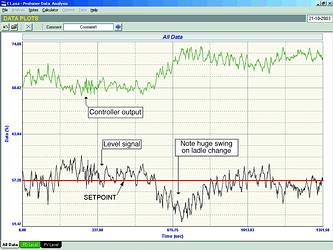
Their tuning was also extremely poor and very slow. Figure 2 shows the 'as found' closed loop test. This test was carried out on a relatively small mould width. It can be seen that the level was far from constant and control was very poor, particularly during the ladle change, which resulted in the level in the tundish dropping down quite far.
Two main difficulties were presented in this work. Firstly, optimisation could only be carried out during actual production, and due to the value of the product the production people were very reluctant to make the step test changes which are required for scientific tuning. This meant that quite a lot of the tuning had to be carried out more by trial and error than scientifically. Only a couple of very small bump tests were possible, but it did allow one to obtain some idea of the process dynamics.
The second difficulty was that the control blocks had to be modified online. This involved very careful testing to establish the true 'as found' tuning parameters already in the controller, so that when the modifications were made, the controller carried on initially with the same effective initial 'as found' parameters.
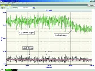
The result of the tests was a dramatic improvement in the control. Figure 3 shows part of a test during which a ladle change was made. It can be seen how well the control could cope with this change. The machine was left running with the new parameters. At one stage during the night shift, the control apparently went unstable. This occurred simultaneously on both strands that were running at the time. There was no apparent reason for this. The only difference was that a different grade of steel was being manufactured. The tuning was slowed down slightly, and performed well after that. The plant was advised that if the same problem occurred again it would be vital to ascertain what had changed in the process. Obviously something had occurred which had caused the dynamics to suddenly change. (This is the type of thing that often needs quite a bit of good detective work to sort out.)
Another problem encountered was that the control with the slightly slower parameters could not cope adequately with speed changes. This was easily solved by slowing down the ramp rate of the changes.
Everything was now fine with control at smaller mould widths. Tests were then carried out with wide mould widths. The control was relatively good at lower machine speeds. However once a certain speed was exceeded it appeared as if the control had gone unstable. The plant personnel certainly blamed the control.
How does one ascertain if a closed loop control loop is in fact unstable? One way is to go and check if the valve is actually oscillating. In this case the movements of the controller output had actually increased proportionally to the swings in level, so it did look unstable. Another way is to slow the control down. If the controller tuning was causing the instability, then slower tuning should allow the process to settle down. This then shows the tuning was probably at fault. If the cycling still continues then the fault must lie elsewhere.
Figure 4 shows such a test. The large cycling can be seen. In the middle of the test as seen in the figure the controller was virtually detuned (almost into manual). The cycling still continued. This proved it is not a control problem, but would indicate that waves have appeared in the mould, possibly standing waves. This observation has also been made by Niemann, Adamy, and Nitshe of Siemens who have done similar work on control of continuous casting machines.
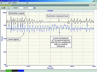
The plant is now investigating causes of this, and will hopefully find a cure. Unfortunately feedback control cannot deal with disturbances like this. The dominant frequency of the waves give a period of about 15 seconds, which is very close to the ultimate period of the control loop. As mentioned in the Loop Signature series, variance of feedback controls deteriorates with frequencies close to ultimate frequency.
For more information contact Michael Brown, Michael Brown Control Engineering, 011 486 0567, [email protected], www.controlloop.co.za
Michael Brown is a specialist in control loop optimisation, with many years of experience in process control instrumentation. His main activities are consulting, and teaching practical control loop analysis and optimisation. He gives training courses that can be held in clients' plants, where students can have the added benefit of practising on live loops. His work takes him to plants all over South Africa, and also to other countries.
| Email: | [email protected] |
| www: | www.controlloop.co.za |
| Articles: | More information and articles about Michael Brown Control Engineering |


© Technews Publishing (Pty) Ltd | All Rights Reserved
 printer friendly version