

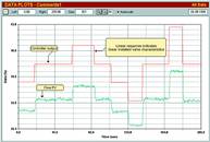
Figure 1 is the open loop test on the flow loop. It should be noted that as the valve appeared extremely linear with a nice fast response and was hysteresis free, the test was only conducted over a flow range from 33 to 53% and the flow loop was then tuned from this test. A final closed loop test with the new tuning was then performed more or less over the same flow region, and the control was robust and reasonably fast. (Purely out of interest the new tuning was about three times faster than the original 'as found' tune, which is pretty normal as we generally find most loops detuned).
The flow controller was then placed on automatic, and set on cascade-remote setpoint so that the level loop could be tuned. An open loop test was then performed on the level loop which is illustrated in Figure 2.
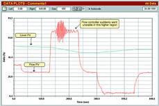
As can be seen in the figure, when the output of the level controller was raised to about 68% the flow came up nicely to setpoint and then to everyone's amazement began to oscillate.
When something like this occurs, it becomes mandatory to retest the errant loop to determine the reason for the instability, so another open loop test was then performed on the flow loop and can be seen in Figure 3.
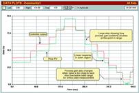
This time the steps were made over the complete operating range of the valve. The response of the valve was satisfactory, showing a good linear installed characteristics – until about 68% of the controller output. Here a sudden and huge increase in process gain can be seen, where the valve moved twice as much as it had previously. It then moved as normal on the following step. Apart from this one can see that there is a slight overshoot on the return step from the top going down, which would indicate possible insufficient power in the actuator to easily overcome static frictional forces. This has been called 'negative hysteresis' and it often results in cycling in closed loop control, with the positioner pushing the valve too far each time it reverses. The process gain also increased near the bottom of the range. Since this is in area where orifice flow measurement is completely inaccurate, and valves generally become very nonlinear near the seat, this area is regarded as a 'no go' control area. There is little one can do about it.
The correct thing to do in a situation like this is to try and find out why the valve moved in such a nonlinear fashion in the one area, and to correct it. Alternatively, one could insert a special linearisation table (or curve shaper) in the output path of the controller to correct the nonlinearity. However, in this case the client felt that the loop was not of sufficient importance to waste too much time on it, and preferred to rather retune the flow controller to take care of the instability. To prevent instability in loops with non-linear characteristics, one should always perform tuning in the region of highest process gain. However, it should be noted that the control response would then be slower in regions of lower process gain. The flow loop was then retuned on the largest step. The Protuner analysis and tuning report is shown in Figure 4.
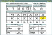
The fastest tune was chosen to try and keep the response in regions of lower process gain from being too slow. The Protuner fast tune allows a gain margin of 8 dB, which is 25% more robust than quarter amplitude damping. However even with this tuning, the flow control tended to oscillate slightly in the upper region with higher process gain. This can be seen in the final closed loop test shown in Figure 5. The first step up shows the response to a setpoint change with the fast tune. The tuning was then changed to the 'slow' parameters and the setpoint then stepped down. It can be seen how the response slowed down as the process variable moved into the region of lower process gain. A further step downwards in setpoint then moved the process into the region of low flow and valve operating very close to seat. As can be seen in Figure 5, the loop then also went into oscillation. Instability in this region is not unusual and one can do nothing about it. It is also not very important in this case, as it is most unlikely that the valve would operate down in this region under normal control conditions. The last two steps of setpoint right up and down, show clearly how the response is nice and fast in the region of higher process gain and slower in the region of lower gain.
One lesson that should be learned from this is never to take linearity for granted, and that one should check the process dynamics over the complete operating range.
Michael Brown is a specialist in control loop optimisation. He can be contacted on telephone (011)486 0567,fax (011)646 2385 or e-mail:[email protected]


© Technews Publishing (Pty) Ltd | All Rights Reserved
 printer friendly version