

I have written several articles about the unique problems I have encountered, specifically in the mining processing industry. This article is about some experiences in a mining operation where recently I was asked to try and sort out a plant which was running in an unstable state, and production was being badly affected.
A new section of the plant had been built and had been designed to replace an old plant that was too small. The aim was to switch over production from the old to the new plant without halting production. Therefore the commissioning had to be on the actual working plant running at full output.
Unfortunately, problems were immediately encountered on the new plant section after the switchover. When I arrived at the plant, I was hosted by a young process engineer who was responsible for the control systems. He told me that he had found some really horrific basic problems, most of which, but not all, he had managed to correct. These included control valves with underpowered actuators, valves that were not proper control valves (even some gate valves), and also really terrible problems with flow measuring elements that were not installed correctly, for example many were installed immediately downstream after the valve instead of upstream (a basic rule that is one of the first things taught to people learning about flow measurement in control systems.)
Fortunately for me, the engineer had managed to correct many of the problems before I arrived, so I was able to go about my job of optimising without having to try and sort out most of the basic instrumentation and valve problems.
The danger of not including C&I; practitioners during the design phase
However, what is noteworthy is that these basic problems arose in a new plant designed by metallurgists and mechanical engineers, who obviously have little understanding of practical measuring techniques and feedback control. It is quite common for mining plants to be created by people with these disciplines who then put in the controls as an afterthought, and very strangely don’t get experienced instrument and control practitioners on board. Some of these people apparently have absolute faith that they know everything necessary about instrumentation and control, and cannot learn anything new.
I have had met mining plant designers and metallurgical process engineers who firmly believe that if there is a PID controller installed then it should be able to control anything, and it only needs to be properly tuned to achieve this, even if the control strategy is completely wrong. I have been told that valves in mining plants must be full line size, even though this usually makes them terribly oversized. Another metallurgist said to me that it is fine to use cheap (and usually inefficient) control and measuring equipment as they do not need to have such good control on metallurgical plants. Another time I was told by a man who designs and builds platinum concentrators that it’s quite acceptable these days to put in small retention time sumps in mining plants, as modern controllers have computers in them that can easily control the level in the sump. He seemed completely unaware of the fact that the sumps are usually there to prevent surges in supply of material to downstream plants due to intermittent upstream production, and that the level control is really only there to prevent the tank from overflowing or running empty. In actual fact the level should be allowed to float around and one should rather keep a constant flow to the downstream units such as to the cyclones. It is all very frustrating to a control engineer that these designers always ‘know better’. A typical remark is that “we have been making plants this way for years, and they work fine”. However, it seems apparent that these designers have apparently never gone out after the plant has been built and spoken to the unfortunate people who have to run them.
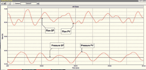
Anyway, back to the present discussion. When I arrived at the plant, the control engineer said they were managing to run it but with some difficulty. The main problem was that they needed to keep the flow of a process fluid supplying the plant very constant, and also at a constant pressure. The system is shown in Figure 1.
Interaction between flow and pressure variables
The flow is measured and controlled via a magnetic flowmeter and variable speed pump. The pressure is measured downstream and a certain amount of fluid is recirculated via a control valve to keep the pressure into the plant at a desired value. This is not an uncommon type of control strategy, but in this case, as quite a large amount of fluid was being recirculated under the running conditions, the two controls were highly interactive. This resulted in a continuous cycle of both the flow and pressure variables, with each of them cycling with a period of approximately 100 seconds and cycle amplitudes of about 10%. This was hitting all the numerous other processes downstream and creating bad production. The recording of the ‘as found’ test is shown in Figure 2.
Interactive cycling of this nature is a phenomenon that occurs quite frequently in complex process control systems, and unfortunately many people do not know how to deal with it. The magnitude of the problem obviously depends on the individual processes and in many cases is not too severe. However, in a case like this it presents quite a big problem.
Dealing with interactive control systems
There are two main ways to deal with interactive feedback control systems. The first is to use a technique called dynamic decoupling, which basically consists of inserting feedforward controls in each loop that cancels out the disturbance being caused by the other loop. This is very effective, but takes time and special engineering.
The second method is much simpler, although not quite as effective. Operators know instinctively how to do it. If two loops are cycling due to interaction, they quickly find out that if one of the loops is placed in manual the cycling stops. Now I sometimes define manual control as ‘the ultimate slow tune’, and basically what one can do is to tune the one loop as fast as possible and then to slow the tuning of the other loop down until the interaction stops. This does work, and in many cases is an acceptable solution.
In this case we tuned the flow loop fast and slowed the pressure loop down so it took about three times longer to respond. This effectively decoupled the loops and solved the problem.
Problems caused by spikes
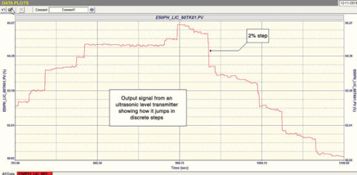
The next major problem we found on the system was spikes in flow on the output of tanks in which the level was being controlled. We found this not to be due to tuning or valve problems, but caused by the measuring transmitters of the ultrasonic type.
Certain types of ultrasonic level transmitters do not give a nice clean continuously variable output, but move in steps. I have not been able to find out why they do this, but would guess that it is due to some sort of statistical filtering system built into them. Alternatively they may also be caused by the computer in the transmitter having an incredibly slow scan rate. Figure 3 shows the recording of the level signal being sent to the controller from one of these transmitters as the level is rising and falling in the tank. The signal moves in slow discrete and often non-uniform steps, many being of about 2% amplitude.
Level control often requires a fairly high proportional gain in the controller if you desire good control that keeps level at setpoint. This gain could be as high as 20, but is typically in the range 5 to 10. Now, if you have a gain of say 10, and the level steps 2%, this will immediately result in the controller output instantaneously stepping 20% – which why the surges in the output flow from the tanks were occurring.
The mine immediately made a decision to replace all these transmitters. In the meantime, we slowed down the tuning with smaller gains and in some cases used lag filters on the transmitters to try and smooth out the signals. This obviously results in less effective control.
Once again I appeal to mining plant designers to get experienced control engineers involved when working on new plant control schemes. It can prevent all sorts of problems and losses in production.

Michael Brown is a specialist in control loop optimisation with many years of experience in process control instrumentation. His main activities are consulting, and teaching practical control loop analysis and optimisation. He gives training courses which can be held in clients’ plants, where students can have the added benefit of practising on live loops. His work takes him to plants all over South Africa and also to other countries. He can be contacted at Michael Brown Control Engineering cc, +27 82 440 7790, [email protected], www.controlloop.co.za
| Email: | [email protected] |
| www: | www.controlloop.co.za |
| Articles: | More information and articles about Michael Brown Control Engineering |


© Technews Publishing (Pty) Ltd | All Rights Reserved
 printer friendly version