



In the previous article dealing with process dynamics, process gain was discussed.Two further important dynamic factors occurring in the majority of process responses are deadtime, and the first order lag.
Deadtime in a process is defined as the amount of time after a change is made in the input to the process before there is any change in the process output measurement. Deadtimes in processes are typically the result of transportation delay.
Figure 1 depicts a mass feeder conveyor, where the belt is moving at a given rate. The process deadtime is the time taken from when the material leaves the hopper until it reaches the measurement transmitter. Processes with long deadtimes compared to the process time lags (see below), require relatively fast integral times and very small proportional gains in the controllers.

Deadtime is the 'enemy' of feedback control, as it results in phase lag, and hence possible instability in a loop that is tuned too fast. To counter deadtime one has to insert less gain in the controller. This means that deadtime-dominant loops (see definition below) have to be tuned more slowly. This is a reason why the D (derivative) parameter should never be used in the control of such processes.
In fast processes, like flow and low capacity or hydraulic pressure loops, the controller scan rate adds deadtime to the process. Therefore controllers with slow scan rates, when used on fast processes, can make these types of processes act as deadtime dominant loops, resulting in the need to detune the controller.
There is a common misconception that deadtime dominant processes cannot be controlled with PID controllers. This is completely incorrect. A PID controller on such a process can be tuned so that the process can fully respond to a step change in setpoint within approximately two deadtimes. However, in reality, if the deadtime is long, this is slow.
In real life situations, the majority of controllers are there to deal with load changes as opposed to setpoint changes. The problem that often occurs in deadtime dominant processes is that load changes occur too frequently and too fast for the controller to be able to catch these changes. In such situations it may be necessary to re-examine the control strategy and to try to find alternatives.
A first order lag is illustrated in Figure 2. It is an exponential response to a step change on the process input. The lag is measured by its 'time constant'. A pure lag reaches 63,2% of its total change in one time constant. The time constant value is not affected by the size of the step. Lags in a response are a function of the resistance and capacitance of the process. In this example, the resistance is the orifice in the valve restricting the gas flow, and the capacitance is the volume of pipe the gas must fill to increase the pressure.
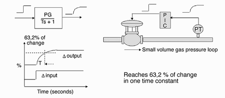
On fast processes like flow, the process dynamics are largely determined by the valve dynamics. Most pneumatically operated valves respond to step changes exponentially, as opposed to electric motor driven valves, which respond in a ramp fashion. The first order lag response is very common, and the vast majority of processes found in industrial control generally incorporate at least one such lag.
The first order lag is also commonly used to provide a 'filter' or 'damping' function in control loops. Most process transmitters and controllers offer a filter feature to allow one to reduce or suppress noise that has entered the process variable measurement. It should be noted that when a filter function is employed in the transmitter, or controller, to 'smooth' the recorded process variable measurement signal, the controller does not act on the true response of the process, as the filter adds lag time to the PV signal. Much will be said about the potential disadvantages and dangers of using filters in a later article in this series.
The relationship between time constant and deadtime is very important. Generally, processes with deadtimes smaller than the time constant of the dominant lag are easier to control. A process with the deadtime smaller than one tenth of the dominant lag may be classed as a 'pure lag only' process which is a deadtime free process.
Without any deadtime, a pure lag process cannot become unstable as the phase angle can never reach 180°. This means it can be can be tuned virtually as fast as one wishes. Typically pure lag processes are encountered in real life on certain self-regulating temperature processes where one lag is significantly larger than any other.
Processes with a deadtime longer than the time constant of the dominant lag are said to be 'deadtime dominant', and are considered more difficult to control. This is due to the fact that one must 'detune' deadtime dominant processes for reasons of stability as discussed above.
It is of significant interest to note that after five years of intensive empirical research in the '30s, Ziegler and Nicholls only managed to come up with fairly 'rough' tuning methods for simple self regulating processes with process gain, deadtime, and lag - and where the lag was larger than the deadtime. Even today, many of the published tuning methods, self tuning controllers, and commercial tuning packages on the market can only deal with similar simple dynamics.
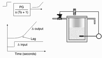
On integrating processes like level controls, the lags are usually insignificant and play little role in the dynamics of the process. However on certain types of integrating processes, particularly like large capacity pressure control systems, and in certain types of integrating temperature processes like end-point control (also commonly referred to as batch temperature processes), a large lag is present which has a significant effect on the dynamics.
Figure 3 illustrates such a process. Instead of the integrating process going straight into a ramp when the balance is disturbed, as in a level loop, it slowly curves up into the ramp as seen in the diagram. This is due to the lag. A noteworthy point is that this is one of the only two cases of process dynamics where one should use the D term in the controller. In this particular case, the D can make a really significant improvement to the control response, typically increasing the speed of response by as much as a factor of four. The value of D is set equal to the time constant of the lag, and this effectively cancels the lag, particularly if the controller is using a series algorithm. (See article on controller algorithms later in the series.)
As mentioned in the previous article in this series, there are many other types of more complicated dynamic responses that are commonly found in industrial processes. These include multiple lags, higher order lags, and positive and negative leads which all play a significant part in the control of such processes. These dynamic factors are beyond the scope of these articles. However, it is essential that people who are serious about optimisation study techniques in dealing with the control of processes with such difficult dynamics. (Our Part 2 course on practical control deals extensively with this subject).
Michael Brown is a specialist in control loop optimisation, with many years of experience in process control instrumentation. His main activities are consulting and teaching practical control loop analysis and optimisation. He gives training courses that can be held in clients' plants, where students can have the added benefit of practising on live loops. His work takes him to plants all over South Africa, and also to other countries.
| Email: | michael.brown@mweb.co.za |
| www: | www.controlloop.co.za |
| Articles: | More information and articles about Michael Brown Control Engineering |






© Technews Publishing (Pty) Ltd | All Rights Reserved
 printer friendly version