

The early days
I grew up in an era when young men were called up for the army, and I did my time on the border. Upon my return, my father asked me if I wanted to study, and my answer was a short 'no', as I felt I needed to do something constructive. I worked in various jobs, including at a feed mill, as a pump rep, and at a chicken abattoir. That was when I realised that without qualifications, I would stay at the bottom. So I started out my career in the instrumentation field as an ‘oupa’ apprentice at the ripe old age of 28 and decided to study further. What a journey it has been, ranging from Sasol to Somchem to Caltex/Chevron, and even a spell in Kazakhstan.
Still a place for simple systems
The field of instrumentation has changed dramatically from the early years to the present. Single loop pneumatics changed to 4-20 mA, while PLCs and DCSs have become a key component of most plants. However, there is still place for pneumatic local control loops in remote areas of a plant due to lack of infrastructure, and they are still used.
Remote areas in a plant do not have the cabling for telemetry, and it is too expensive to install for a few local field loops only. However, instrument air is usually available, and a local or field pneumatic controller and loop does the trick. This is relevant because of the challenges still faced by manufacturing plants and mines at remote sites in Africa. They need something basic and simple and cheap, and the pneumatic local or field loop is cheap. On the other hand, instrument air is very costly to produce for the following reasons:
• Driers (desiccants) are required to dry the air to a specified dryness (dew point), otherwise the pneumatic instrument internals will rust.
• Air has to be filtered properly, otherwise dust particles and wet instrument air form a cement-like goo and block air orifices, rendering them useless.
• Water vapour will drop out if the dew point drops below a certain value, and the water collecting at low points will freeze in sub-zero temperatures, constricting air flow. When I was in in Kazakhstan the design temperature range was -40 to 40°C.
Electronics in hazardous environments
With the transformation from pneumatic telemetry to 4-20 mA ‘wires’ telemetry, some important issues arose. Electronic signals to and from the field or plant in hazardous areas where explosive gases were present needed to be conditioned or limited in order to prevent an ignition source from causing an explosion. Luckily there were different systems, techniques and installations available to deal with this. They included intrinsic safety (exi), explosion proof/flame proof (exd), non-incendive (exe), non-sparking (exn) and purging (exp).
Even today pneumatic telemetry is still more suitable in the explosives and propellants industries because electronic telemetry to and from the field is an ignition source that can lead to fatal consequences.
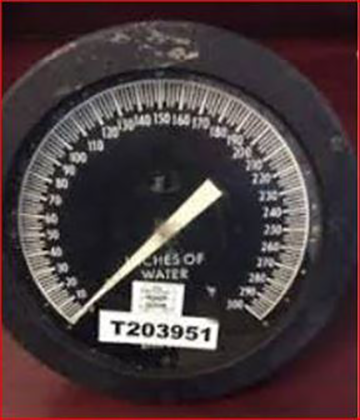
To give an example, a modern plant that I worked on used intrinsically safe installation techniques on its instrument installations, but had a unique problem measuring the windings temperatures of a high voltage ammonia compressor electric motor. The motor had an explosion-proof enclosure. If there was a short in the windings, the high voltage could flash through via instrument wires to the control room and short or blow up the marshalling cabinets and control system. This arc back flash could also cause an explosion if hazardous gases were present, with the possibility of fatal incidents. To prevent any arc from flashing through, Foxboro Model 12 pneumatic temperature transmitters with capillaries were inserted into thermowells embedded in strategic positions in the windings. They transmitted the winding temperature via pneumatics and PVC tubing to a 20 to 100 kPa pressure to a 4-20 mA current transducer situated about three metres away. In this case, pneumatics prevented flash-through and a possible incident by acting as an isolator.
Replacing old instruments
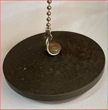
One of my jobs as an apprentice in the early 1980s, was to remove antiquated instruments from the field. The old Foxboro Model 27 was replaced with a Foxboro Model 19A pneumatic DP cell for transmission and display on a Foxboro Model 40 recorder and controller. The recorder/controller was situated in a control room dedicated to the plant area.

The ½” stainless steel instrument tubing ran all the way from the field isolation block valve to the service passage behind the control panel in the control room to a Mercoid pressure switch. This created a potentially very dangerous situation due to possible leaks causing a flammable mixture, which could be ignited by switch arcs or lights in the control room. In this case the contact was hermitically sealed so that the arc was not an ignition source.
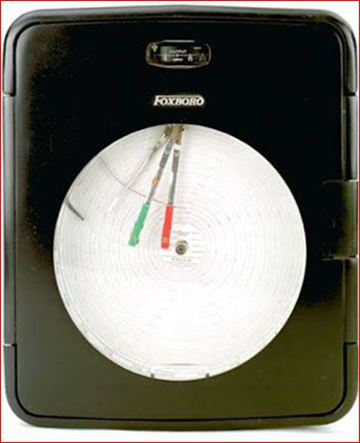
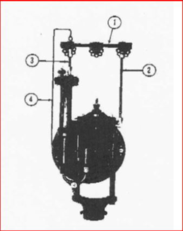
The pneumatic Foxboro Model 40 recorder and controller was a brilliant piece of work for its day, and was the Rolls Royce of the time. It had proportional, integral and rate utilising bellows and small tanks with bleed valves. The flow charts were available in linear or square root.
Then and now
In the old days, pneumatic transmitters and controllers had pneumatic relays that needed to be recalibrated during shutdowns or routine schedules. Additionally, the complete instrument needed to be recalibrated and resprayed. It had to be removed and transported to the workshop to perform these functions, a time-consuming and costly exercise. Calibration was performed on mercury manometers. Instrument personnel were trained in an apprenticeship and had to write a trade test to show that they had the proficiency to perform fault-finding, and repair and replace any faulty or defective instrument components.
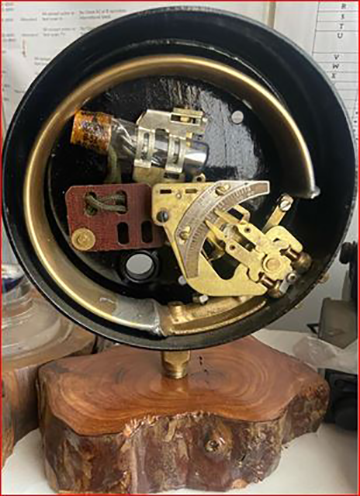
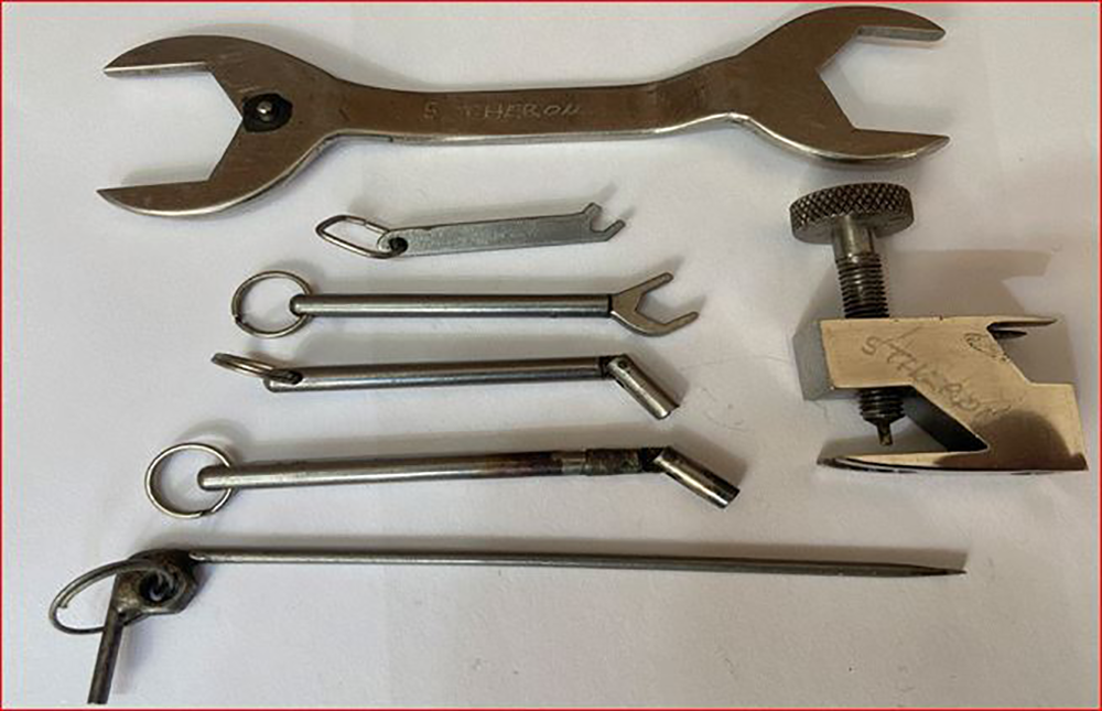 Apprentice/instrument mechanic calibration tools.
With the advent of electronic transmitters, the instruments were calibrated on a manometer in the workshop as well. If the instrument was faulty, the electronic card was replaced with a new card. Basically, instrument personnel became component and instrument replacers.
In later years, smart instruments appeared on the market. Instrument personnel would then arrange with the control room operator to switch the control loop to manual, with the instrument remaining in situ. A hand-held communicator was then connected to the instrument via two wires to check the calibration or change the range of the transmitter. When complete, the loop was switched back to automatic. If the instrument or unit was faulty, for example if differential pressure cell sensors failed or overheated, any faulty cards were replaced on the complete instrument as a unit. An advantage of smart instruments was that diagnostics became available online.
Today’s technology is a far cry from bygone years, when pneumatic telemetry consisted of a single 1/4” tube, bundled tubing and pneumatic controllers and recorders. Nowadays we have 4-20 mA signals, fibre optic sensing and telemetry, internet, bus systems, radio links via a dedicated radio transmitter and receiver, and GSM. Panel mounted pneumatic controllers and recorders have been replaced by stand-alone electronic controllers, PLCs and DCSs in the control room. The modern process automation plant is a very different place indeed.


© Technews Publishing (Pty) Ltd | All Rights Reserved
 printer friendly version