Split-range control is typically used in industrial processes for controlling pressure, temperature and flow in cases where it is necessary to control a two-mode operation, i.e., using two or more final control elements, commonly valves. For example, split-range control is used to maintain a vessel’s temperature where there are both heating and cooling controls.
Normally only one controller is used, and its output is split so that the valves operate in ranges dictated by the loop designer. Typically, the one valve may be ranged to be fully open when the controller’s output is at 0%, and be fully closed when the output reaches 50%, whilst the other valve starts opening at 50% output and is fully open when the output reaches 100%. However, the ranging of each valve and its action depends on the control strategy that is being implemented.
In my experience, split-ranging is usually implemented poorly for various reasons, one of which is that the designer does not take the process gains which will occur when each valve is open into account. They should be the same if the controller tuning is going to be correct in each case, otherwise different tuning should be implemented in the controller to cater for the range of each valve.
The example presented here is of an important drum pressure control in a refinery. There were two valves employed in a split-range configuration, one to increase the pressure and the other to reduce it. The split-ranging was done on the same basis as that described above. Both valves were supposed to be fully closed when the controller’s output was at 50% – the one to reduce pressure was supposed to start opening as the controller’s output went lower than 50%, and the other (whose purpose was to increase pressure) was supposed to start opening as the controller’s output went higher than 50%.
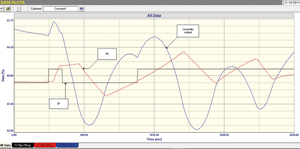
The operators complained that if the setpoint was at about 50% (the value at which they wished to run the drum), the pressure became uncontrollable and cycled all over the place. The closed-loop ‘as found’ test (with existing tuning parameters) confirmed what the operators were saying, and this is clearly seen in Figure 1.
Pressure control is one of the processes that can be self-regulating or integrating, and this was discussed in detail in one of my previously published Loop Signatures articles (www.instrumentation.co.za/10919r). It is sometimes very difficult to determine which type it is. However, in this case it could be seen quite quickly that the process is definitely very much an integrating type.
Integrating processes are those where the input to the process must be equal to the output in order to keep the PV constant. If they are not equal, the PV will ramp either upwards or downwards, but will not remain steady. This is typified by level control processes where one has to keep the flows going into and out of the vessel equal, if the level is to be held constant. If the one flow is different to the other, the vessel will either fill or empty. This is known as a ‘balancing’ control, and the value of the controller output when the input equals the output is known as the ‘balance point’.
In Figure 1 it can be seen that at the start of the test, the process was more or less in balance, with the PV remaining constant. However, when a setpoint change was made, the process reacted in a very strange fashion and the PV ended up cycling around in a very strange sawtooth waveform, whilst the PD (controller output) went into an almost sinusoidal cycle.
When performing an analytical and tuning test in open-loop (manual mode) on an integrating process, one gets the process into balance and then makes a step change on the PD so the ramp rate can be analysed. Once you have a nice ramp, you return the PD to the balance point and then make a step in the other direction to get a ramp in the opposite direction.
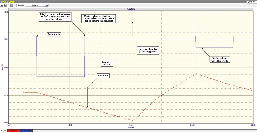 Figure 2. Practical analytical and tuning test in open-loop mode on an integrating process.
In our test shown in Figure 2, we started off with the PV in balance and then stepped the PD down by 5%. This resulted in a very nice, constant ramp. When we then stepped the PD back to the original balance point, the ramp not only didn’t balance out and become constant, but in fact continued ramping at the same rate. On a normal loop with only a single valve, this would indicate that the valve hadn’t moved and it was probably suffering from severe hysteresis. We then stepped the PD up a further couple of percent and the PV then started ramping up again. This process was repeated in subsequent steps, as can be seen in Figure 2.
Further tests in open-loop (not shown here) were then carried out and it was determined that no control action occurred within a band as large as roughly ±3% around the value where the two valves were both closed. This was probably because either the valves had not been accurately stroked to start opening immediately their input signals rose above zero, or the valves were not able to operate at very low openings, which is a very normal thing for valves that are not of the highest quality. This resulted in the cycling backwards and forwards through the deadband, as no balance point could be obtained.
We did manage to get several reasonably good and consistent tests to analyse the ramp rate and allow us to determine reasonable tuning parameters. These were
What was really interesting was that the new tuning parameters did allow the control to work in a more or less stable fashion, and could get the PV within a few percent of the setpoint. However, the valves would have to be sorted out if they really needed to get better control. A final closed-loop test with the new tuning is shown in Figure 3.
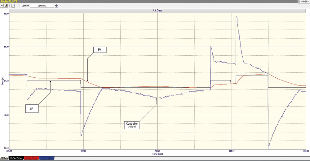 Figure 3. Closed-loop test after successful tuning of parameters.
This is another very interesting example that shows how important it is to analyse loops properly to understand what is causing problems, as opposed to the old misconception that tuning will sort out loop problems – and this is substantiated by having witnessed people spend inordinate amounts of time playing with tuning instead of analysing the loop. It also shows how important it is in split-range control to ensure the valves are working properly, particularly at the point where the one takes over from the other.
About Michael Brown

Michael Brown is a specialist in control loop optimisation, with many years of experience in process control instrumentation. His main activities are consulting and teaching practical control loop analysis and optimisation. He now presents courses and performs optimisation over the internet.
His work has taken him to plants all over South Africa and also to other countries. He can be contacted at: Michael Brown Control Engineering CC,
| Email: | [email protected] |
| www: | www.controlloop.co.za |
| Articles: | More information and articles about Michael Brown Control Engineering |


© Technews Publishing (Pty) Ltd | All Rights Reserved
 printer friendly version