


The widely known EtherCAT Device Protocol, often referred to simply as the EtherCAT protocol, is used at the field level for I/O communication within a machine or machine part. Special features are, among others, the highly accurate determinism with very low cycle times (down to <100 μs), precise synchronisation for drive and measurement applications as well as low cabling and commissioning costs when using the technology at the I/O level. The process control level requires further communication options in order to operate a plant or a factory. EtherCAT with the EtherCAT Automation Protocol offers a solution to this.
The devices at field level are controlled by a higher-level controller. Large plants such as in the automotive industry incorporate numerous machine lines. Here, the controllers of each area of the plant need to exchange data and, under certain circumstances, the exchange of data between I/O devices from different parts of the plant may be useful.
This results in the following requirements for a communication protocol to be used at production control level:
* Data exchange between EtherCAT masters (master-master communication) = data exchange at controller level.
* Data exchange between EtherCAT master and visualisation.
* Connectivity of higher-level controls to devices in lower-level EtherCAT segments (routing).
* Data exchange between EtherCAT masters and other devices, such as configuration tools.
Additional requirements:
* Standard Ethernet communication interface.
* No strict requirements for cycle time and synchronicity.
* Cyclic communication in the millisecond range.
* Use of standard infrastructure elements such as switches for the networking of devices.
These requirements are met by the EtherCAT Automation Protocol (EAP), which strengthens the vertical integration of EtherCAT throughout the overall system.
EtherCAT protocol types
The EtherCAT protocol can be transmitted via Ethernet (EtherType 0x88A4), via UDP (User Datagram Protocol, UDP port 0x88A4) or via TCP (Transmission Control Protocol, TCP port 0x88A4). Here, the transmission medium is irrelevant: fast Ethernet or Gigabit Ethernet connections via copper or optical fibre are just as possible as the use of the protocol via a wireless connection. This way, it is possible to integrate even complex parts of the plant that cannot be connected via a fixed cable (eg, floor conveyor, rack storage and retrieval systems).
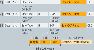
The EtherCAT frame appends itself to the user data in these telegrams. The header of the EtherCAT frame specifies the EtherCAT protocol type.
EtherCAT slaves that are connected to an EtherCAT master always use the EtherCAT Device Protocol.
For the implementation of the protocol, an EtherCAT communication chip, the EtherCAT Slave Controller (ESC), is used in the EtherCAT slaves. This exclusively evaluates telegrams of type 1. Cyclic and acyclic data can be transmitted in an EtherCAT frame with this type.
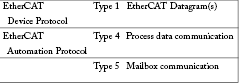
Types 4 and 5 are used for the EtherCAT Automation Protocol. If process data follow, then type 4 is used; in the case of mailbox data, type 5 is in the EtherCAT frame header. The mailbox protocols (CoE, SoE and FoE), as already used with the EtherCAT Device Protocol, can similarly be used with the EtherCAT Automation Protocol.
EAP message routing
Message routing must be possible from the configuration tool via the EtherCAT master to the EtherCAT slave, so that master devices can exchange data with one another or, for example, so that a configuration tool can set para-meters in a drive in the lower-level EtherCAT segment.
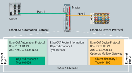
To this end, the EtherCAT Mailbox Protocol AoE (Automation Device Protocol over EtherCAT) is used. This protocol is advantageous because it is capable of routing and can therefore be passed through several levels in order to reach the lower level object directories.
Each Ethernet port in the master is implemented as an AoE device and has its own AoE NetID assigned. Routing from one port to another is performed by an AoE router in the master, which is similarly assigned an AoE NetID. Any port or AoE device and the associated information can be accessed via the AoE NetID. The information that will be made available to the network is structured in object directories. Their precise content differs depending on the task of the AoE device/port.
Object directory
An object directory is a list of variables and parameters. Each entry is addressed via an index of its own and possibly via a sub-index. The entire index space is subdivided into several ranges. The separation of the index space into defined ranges makes the structuring of the data clear. Moreover, this is the basis for the use of algorithms with which the collation of the process data (PDO configuration and PDO assignment) is organised.
Profile-specific range for the EAP
The profile-specific range from index 0x6000 onwards is defined by so-called device profiles. Corresponding device profiles have been specified for many classes of devices (drives, I/O devices). The Modular Device Profile (MDP profile number 5001) is used for the EAP and defines the use of the index space. Special classes of devices are classified into this grid by sub-profiles (eg, for gateway devices). The EtherCAT Automation Protocol has its own sub-profile number (1000) like the EtherCAT Device Protocol (1100) for the EtherCAT master function to the lower-level EtherCAT segment. The AoE router has the sub-profile number 9000.
On a master that supports both the EtherCAT Automation Protocol and the EtherCAT Device Protocol, the ports to the respective network have their own object directory with the corresponding sub-profile number.
Sub-profile 1000 – EtherCAT Automation Protocol
The object directory for sub-profile 1000 is used for the configuration of the communication relationship between two EAP devices. It describes the process data, as used for the EAP.
Sub-profile 1100 – EtherCAT Device Protocol
The object directory of the EtherCAT segment lists all connected slaves. A slave is described here in the object directory as a module.
Sub-profile 9000 – EtherCAT Router Information
The router object directory contains a list with available device interfaces and their AoE NetIDs.
EAP – cyclic data exchange
The exchange of process data in the EAP can take place following either the ‘Pushed’ or the ‘Polled’ principle. In ‘Pushed’ mode each communication device sends its data cyclically or in a multiple of its own cycle. The receiver can be configured to specify which data should be received from which sender. The configuration between the sender and receiver data is performed via the object directory according to sub-profile 1000.
In ‘Polled’ mode the data is queried by the devices. To this end, a device, frequently the higher-level master computer, sends a telegram to the devices to which these reply with their own telegram. This also makes it possible to synchronise the devices.
Structure of the process data
The content of a process data telegram is described in the same way as the process data of an EtherCAT slave. A telegram corresponds to a SyncManager area, so that the structure of the process data of a telegram is determined via the PDO assignment and PDO configuration.
A device defines its output variables (Tx process variables) in the index range from 0x6000. An index is used for each variable (variable 1: 0x6000, variable 2: 0x6001, etc). The name, length and variable type, eg, process or diagnostic data, are combined with the actual value of the variable. Only the variable value itself is transmitted in the process data telegram.
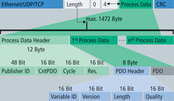
The process variables can then be grouped arbitrarily with the aid of the Tx Mapping PDOs from 0x1A00. A variable can also be transferred into several PDOs. The structures of variables described via the mapping are combined with a variable ID, version (Version) and age (Quality). This is done in the Tx process data range from 0xD000.
The process data must now be assigned for the transmission of an Ethernet frame. The assignment and order of each process data is defined via the assign objects in the range from 0x8000.
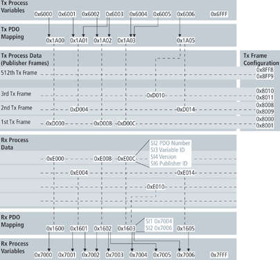
On the receiver side, the sender of the received frames is determined by the publisher ID in the frame header. With this, the variable ID and version from the PDO header, the receiver can find the Process Data Index (from 0xE000) containing the reference to its internal target variable. Thus, the index of the target variables, in which the received variable value is stored as an input variable, is determined via the mapping PDO found (from 0x1600).
The configuration of the process data structure at the receiver side is arbitrary, as at the sender side. The index assigned to an Rx process variable is independent of the index of the Tx process variable. Since the output and input variables are pre-configured, the establishment of an additional connection before the beginning of communication is no longer necessary.
EAP – acyclic data exchange
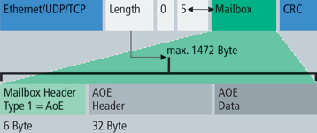
In order to configure the output and input variables and to access the object directories of the master or those of the EtherCAT slaves, acyclic access is enabled to these. To this end, the AoE (Automation Device Protocol over EtherCAT) protocol is used. This allows multiple object directories to be addressed.
A telegram of type 5 (mailbox communication) is used as the transport protocol. The structure of the frame is identical to the mailbox communication within an EtherCAT segment.
The mailbox protocols CoE, SoE and FoE can in turn be mapped on the AoE protocol. As a result, a configuration tool can be connected to the master, for example, in order to access a drive in the EtherCAT network for configuration purposes.
Example of plant automation with EAP
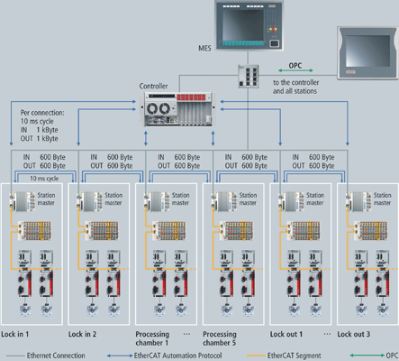
The production of solar modules involves a large number of process steps, for which marking and identification systems, measuring units and special handling modules are used.
The conveyor system used is divided into as many as 14 process islands, wherein each segment is equipped with a control computer and an operating computer. Furthermore, Control Panels can be connected as necessary at any point on the production line.
The exchange of data is realised through the EAP. Each station exchanges status and control information bi-directionally with both the previous and next station: 600 bytes in each direction with a cycle time of ten milliseconds. Added to this is the communication with the control computer, which additionally exchanges up to 1 Kbyte of data bi-directionally with each station.
http://instrumentation.co.za/+C15490
For more information contact Kenneth McPherson, Beckhoff Automation, +27 (0)11 795 2898, [email protected] , www.beckhoff.co.za
| Tel: | +27 11 795 2898 |
| Email: | [email protected] |
| www: | www.beckhoff.com |
| Articles: | More information and articles about Beckhoff Automation |


© Technews Publishing (Pty) Ltd | All Rights Reserved
 printer friendly version