

Industrial Ethernet is more than just a marketing phrase; it describes the environment in which an Ethernet device must operate. Hardened Ethernet switches are a complete rethinking and redesign of office-based Ethernet components. Electronics in extreme industrial environments can be subject to high levels of EMI, heat, and moisture, as well as dust, dirt, and corrosive chemicals. In addition, required levels of availability may exceed those for a commercial environment. It is never good when the network goes down in an office, but it is likely to have a more serious impact if an electrical blackout causes hundreds of thousands of subscribers to lose power.
There are a number of components to creating a hardened switch, but the most significant are:
* Fibre media configurability.
* Metal cases for electrical shielding.
* Dusty, dirty, damp, or corrosive environments.
* Cooling options.
* DC power.
* Redundancy options.
Fibre media
Fibre has traditionally been employed as the backbone media, but is often the best choice for noise immunity and security within a complex such as a substation. A typical media line tap will not work on fibre. Ethernet switches that integrate fibre within a modular structure can make the installation and future upgrades easier and more economical. Fibre operates over a much greater range than copper, based on fibre media type, drivers and receivers, and without repeaters that must be employed with RJ-45 cabling. Security issues aside, fibre, along with a metal case for the electronics, is the answer to high EMI levels in industrial environments.
Recently media costs for copper and fibre have begun to converge, installation costs are similar, and trained personnel are in place. It is the rest of the hardened picture that separates the boxes that are going to survive in hostile locations from the ones that have simply had a quick adaptation from their commercial kin.
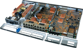
Metal cases
While many commercial Ethernet switches give more thought to colour pallet and aesthetics for case design, industrial hardened boxes consider corrosive chemicals, high particulate counts, and EMI noise.
Industrial Ethernet devices are located in a variety of demanding environments. Ethernet switches, for example, are located in temperature-uncontrolled locations such as mines, cell towers, traffic control boxes, and remote substations. Devices can be exposed to moisture, chemicals, particulate matter, insects, and other environmental contaminants in mines, mills, telecommunications relay stations and other harsh environments. Conformal coatings assist in eliminating problems from moisture and corrosives.
Many sites are unattended, making reliability, especially under extreme operating conditions, a critical component in product choice.
Keeping it cool
Out-of-doors conditions for Ethernet switches, particularly those where the units will have only infrequent visual checks, may mandate sealed, free-convection-cooled equipment. Environmental factors such as dust, insect penetration, and moisture can play havoc with forced-convection-cooled (fan-cooled) systems, even when air filters are designed in. Equally, indoor systems that are in areas where there is a lot of dust, dirt or other contaminates, such as in mines, or where forced-convection device noise is unacceptable, such as on a movie studio set, may benefit from a sealed system with free convection cooling.
Electronics cooling is getting increased attention as Ethernet products migrate into industrial settings. The debate between free-convection and fan cooling is still raging, but a variety of factors including the application and environmental considerations should be the prime deciding factors.
Typically, a system's MTBF is calculated by determining the failure probabilities of the individual components within a product design, and then calculating the composite reliability for all of the components in the entire product. However, with regard to operating temperature, this may be insufficient.
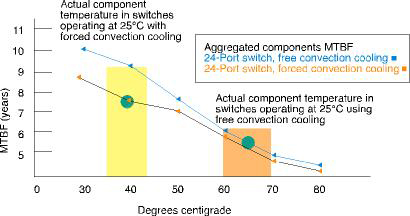
Using component MTBF factors only, free-convection designs (using rack-mount switches here for comparison) appear to operate with normal reliability in environments with ambient temperatures for the switch box of up to 40-50°C. However, when the components are incorporated on circuit boards inside metal boxes with restricted air flow, measured internal temperatures are much higher. While forced-convection devices may be viewed as additional sources of failure, they also reduce the internal temperature delta to ambient. To get a complete picture of the effects of forced-convection cooling, it is instructive to calculate and measure the MTBF reliability gains vs. the reliability losses for forced-convection designs.
The two curves in Figure 1 show calculated MTBFs for the aggregate components in rack-mount switch designs, with and without forced-convection devices, for a range of temperatures of 30°C to 80°C. The space between the two curves is the difference in electronic component reliability for a free-convection design (the top line) vs. a forced convection design. The vertical bars show calculated internal temperatures in rackmount switch designs operating in a comfortable room ambient of 25°C. For the forced convection design (left vertical bar), the internal components experience a temperature delta above room ambient of 15°C and therefore operate at 40°C. The green dot on the left shows the expected reliability of a switch design using forced convection, when the true internal heat of the components is overlaid on the curve. When dirty air and fan noise are not dominant concerns, fan-cooled devices provide better reliability results.
In 2006, thermal design advances for networking products in industry include isolation of the power supply (a prime source of heat generation) and heavy-duty heatsinks of highgrade copper for better heat dissipation, preferably mated to the outer housing for additional heatsinking. However, we believe that the resolution of the fan/no-fan cooling debate will still reside within the environmental aspects of the application.
Power options
Recent research indicated that preferred voltage ranges in substation automation were 88-150 V d.c. and 36-60 V d.c., but >125 V d.c., <48 V d.c. and 115 or 230 V a.c. were also utilised. Ideally, the customer will have the option of choosing the required voltage to match the equipment power source available. Modular systems that allow the customer the choice of power supply along with other configuration characteristics can provide the flexibility required for a variety of deployments.
Redundancy is never redundant
Once the sheer mechanics of operating in an industrial environment are considered, additional hardware and software features that add to redundancy can be critical to success. Since many of the applications requiring hardened devices are also applications where downtime is not an option, built-in redundancy features are important. In a network, a single path to a device or sub-network is also a single point of failure. Several strategies can be employed to solve this problem. Ensuring that key components are robust and highly reliable is one step. Permitting more than one path to every device is another.
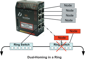
Careful design of network topology is a strategy to ensure maximum uptime. In power substations and other facilities at the edge of the industrial network, ring topology designs can provide simple but effective redundancy. Ring networks, which comprise a number of point-to-point links, provide an added benefit in lower wiring distances and costs, and the signal is reshaped and re-sent from each device to its neighbour.
Redundant ring solutions provide two points of connectivity in a ring with one forwarding port, and one backup or alternate port that becomes the forwarding port when the primary port becomes inoperative because of a broken link. With Rapid Spanning Tree Protocol (RSTP) and other standards-based and proprietary strategies, recovery performance is now at a point where it can meet the recovery-time requirements for almost any application.
In Ethernet LANs, dual-homing is a network topology that adds reliability by allowing a device to be connected to the network by way of two independent connection points (points of attachment). One access point is the operating connection, and the other is a standby or back-up connection that is activated in the event of a failure of the operating connection.
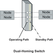
A dual-homing switch, with two attachments into the network, offers two independent media paths and two upstream switch connections. Loss of the link signal on the operating port connected upstream indicates a fault in that path, and traffic is quickly moved to the standby connection to accomplish fault recovery.
Summary
Hardened Ethernet is made up of many components, combined in a way that works for the application at hand. Some of the key points to remember are:
* Ethernet is the accepted standard in IT networks worldwide. However, its inclusion in industrial applications that suffer from hostile environments, unattended operation, and, increasingly, a high level of security, requires a careful redesign of the box that houses the key components.
* Fibre provides noise and EMI immunity, long distance connections, high bandwidth, and security with a minimum increase in cost. Fibre integrated within the Ethernet switch extends that protection within the switch.
* Metal cases shield against EMI. Fully sealed metal cases with conformal coating are required in high particulate or caustic environments.
* A choice of forced or convection cooling that keeps components cool means a flexible approach to solving the problems of unfriendly environments. The application environment is the best determinant for the cooling choice.
* A choice of power input ranges, including dual-source DC, provides flexibility in matching the product to the application.
* Redundancy within the network structure can help reduce downtime due to single component failures.


© Technews Publishing (Pty) Ltd | All Rights Reserved
 printer friendly version