

The ubiquitous problem with every plant is the interface of plant measurement signals to the monitoring and control systems. Unfortunately for many plants this is the single biggest area of weakness and with the success of the organisation depending on these measurements, more attention should be afforded to the integrity of signal conditioning systems.
The problems faced by these systems are numerous:
* Aged cabling.
* Long cable runs.
* Earth loops.
* Interference from other plant devices.
* Floating earth potentials.
* Isolation of signals from PLC, SCADA and DCS.
* Legacy instrumentation.
* Isolate grounded equipment.
* Adding instruments to existing loops.
* Poor design.
* Converting current loops into accurate 1-5 V.
* Protecting against open circuit loops.
* Load dependency calibration.
A compendium of common problems is addressed using loop powered isolators (LPIs) in this two-part article.
In Part 1 four applications will be looked at and in Part 2 in next month's issue, a further six applications will be dealt with.
Application 1: Using the LPI to isolate a powered 4-20 mA transmitter output from a resistive load
This is the basic circuit for inserting a loop powered isolator into a current loop. The LPI can simply be 'cut' into any existing current loop to isolate the current transmitter from the load.
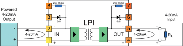
Note: The 'IN' side of the LPI is always connected to the side of the loop supplying the loop power.
The LPI will consume less than 3 V of the available loop voltage. This is equivalent to inserting less 150 Ω of additional resistance into the current loop.
To determine the maximum loop resistance that you can tolerate in your cabling, apply the following formula:
RMAX = RT - RL - 150
where:
RMAX is the maximum resistance in the loop without causing measurement error (in Ω).
RT is the maximum load resistance that the current transmitter can drive (in Ω).
RL is the total resistance of all loads in the loop (excluding the LPI) (in Ω).
For reliable operation over the long term, you should design for less initial cable resistance than this maximum value. This provides a safety factor to account for increase in resistance of terminations and wiring with age or weathering.
A sensible value to use for this safety factor would be 100 Ω (equal to 2 V at 20 mA).
Application 2: Using the LPI to isolate a field-mounted 4-20 mA two-wire transmitter from a PLC, RTU or DCS
This is the basic circuit for isolating a field-mounted two-wire transmitter from the control circuitry using an LPI. The LPI can simply be 'cut' into any existing two-wire current loop to isolate the transmitter from the panel power supply.
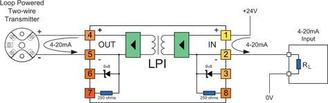
NOTE: The 'IN' side of the LPI is always connected to the side of the loop supplying the loop power, so in this application the two-wire transmitter is connected to the OUT terminals of the LPI.
Because of the 2 mm² wire size capability of the LPI terminals, the LPI can also act as the field interface terminals, saving you the extra termination and wiring cost. For multiple loops where space is a concern, use the LPD dual module. (See Applications 7, 8 and 9 in Part 2 of this article).
The LPI will consume less than 3 V of the available loop voltage. This is equivalent to inserting less 150 Ω of additional resistance into the current loop.
To determine the maximum loop resistance that you can tolerate in your cabling, apply the following formula:
where:
RMAX is the maximum resistance in the loop without causing measurement error (in Ω).
VSmin is the minimum voltage of the power supply used to drive the loop (in V).
VTmin is the minimum voltage required by the two-wire transmitter for operation (in V).
RL is the total resistance of all loads in the loop (excluding the LPI) (in Ω).
For reliable operation over the long term, you should design for less initial cable resistance than this maximum value. This provides a safety factor to account for increase in resistance of terminations and wiring with age or weathering.
A sensible value to use for this safety factor would be 100 Ω (equal to 2 V at 20 mA).
Application 3: Using the LPI's internal resistor with a two-wire transmitter to provide 1-5 V to your PLC/RTU/DCS
There are many cases when using 4-20 mA inputs to your PLC or RTU or DCS is inconvenient. For example:
1. Your analog input does not support 4-20 mA, and mounting an external resistor is inconvenient.
2. Your analog input has plug in terminals, and you do not want to lose power to your field transmitter or disrupt the loop if the terminal block is unplugged.
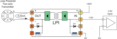
In these cases you can use the internal resistor on the IN side of the LPI to conveniently convert your 4-20 mA signal into a 1-5 V signal. For the most accurate result, ensure that the 0 V reference of the LPI (terminal 8), and the 0 V reference of your analog input are referenced to the same point. Note: The 'IN' side of the LPI is always connected to the side of the loop supplying the loop power, so in this application the two-wire transmitter is connected to the OUT terminals of the LPI.Because of the 2 mm² wire size capability of the LPI terminals, the LPI can also act as the field interface terminals, saving you the extra termination and wiring cost.
The LPI will consume less than 3 V of the available loop voltage. This is equivalent to inserting less 150 Ω of additional resistance into the current loop.
To determine the maximum loop resistance that you can tolerate in your cabling in this application, apply the following formula:
where:
RMAX is the maximum resistance in the loop without causing measurement error (in Ω).
VSmin is the minimum voltage of the power supply used to drive the loop (in V).
VTmin is the minimum voltage required by the two-wire transmitter for operation (in V).
For reliable operation over the long term, you should design for less initial cable resistance than this maximum value. This provides a safety factor to account for increase in resistance of terminations and wiring with age or weathering.
A sensible value to use for this safety factor would be 100 Ω (equal to 2 V at 20 mA).
Application 4: Using the LPI's internal resistor with a four-wire transmitter to provide 1-5 V to your PLC/RTU/DCS
There are many cases when using 4-20 mA inputs to your PLC or RTU or DCS is inconvenient. For example:
1. Your analog input does not support 4-20 mA, and mounting an external resistor to convert the signal to 1-5 V is inconvenient.
2. Your analog input has plug in terminals, and you do not want to lose power to your field transmitter or disrupt the loop if the terminals are unplugged.
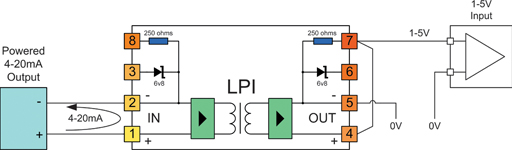
In these cases you can use the internal resistor on the OUT side of the LPI to conveniently convert your 4-20 mA signal into a 1-5 V signal.
For the most accurate result, ensure that the 0V reference to the LPI (terminal 5), and the 0V reference of your analog input are referenced to the same point.
Note: The 'IN' side of the LPI is always connected to the side of the loop supplying the loop power, so in this application the four-wire transmitter is connected to the IN terminals of the LPI.
Because of the 2 mm² wire size capability of the LPI terminals, the LPI can also act as the field interface terminals, saving you the extra termination and wiring cost.
The LPI will consume less than 8 V of the available loop voltage. This is equivalent to inserting less than 400 Ω of resistance into the current loop.
To determine the maximum loop resistance that you can tolerate in your cabling in this application, apply the following formula:
RMAX = RT - 400
where:
RMAX is the maximum resistance in the loop without causing measurement error (in Ω).
RT is the maximum load resistance that the current transmitter can drive (in Ω).
For reliable operation over the long term, you should design for less initial cable resistance than this maximum value. This provides a safety factor to account for increase in resistance of terminations and wiring with age or weathering.
A sensible value to use for this safety factor would be 100 Ω (equal to 2 V at 20 mA).
For more information contact Ian Loudon, OmnIflex, +27 (0) 31 207 7466.
| Tel: | +27 31 207 7466 |
| Email: | [email protected] |
| www: | www.omniflex.com |
| Articles: | More information and articles about Omniflex Remote Monitoring Specialists |


© Technews Publishing (Pty) Ltd | All Rights Reserved
 printer friendly version