

As network technology advances, many companies are designing new systems or modifying existing ones to take advantage of the many benefits that new technology can offer: increased speed and data handling capacities, more flexible system architectures and lower connectivity and integration costs. However, these benefits cannot be fully realised without proper network design specification, installation, and operational validation.
Some installation problems are easily identified and corrected during system commissioning. However, some problems may be misleading or hard to identify. These include: slow network response, excessive retries, excessive traffic and high status register error counts.
The root cause of network problems
Industry studies show that installation and media related problems account for 70-90% of the downtime occurrences in operating networks. A problem can range from a delay caused by multiple retries, to intermittent communication loss errors, to a catastrophic network failure. In an industrial environment, any of these problems can result in lost data and increased troubleshooting time, which can negatively impact commissioning and/or production.
When a network is improperly installed, or incorrect media is used, data signal transmissions become degraded, which is the root cause of most network problems. The degradation prevents proper recognition and processing by system components. To prevent the common industrial network problems and make operation more robust, one needs to understand what causes degradation and correct problems so degradation falls within allowable limits.
All networks are designed to allow some level of degradation. Open network agency specifications such as ODVA, CNI, and TIA/EIA define allowable signal measurement ranges for each network type. Problems occur when the installation-related problems cause degradation that exceeds these specified limits.
It is important to note that a network can be installed and operated without knowing all specifications. Installation and technical manuals incorporate and 'translate' specifications and requirements into acceptable common practices. However, acceptable common practices are not always followed.
Sources of signal degradation
To understand the primary cause of signal degradation, we need to apply basic transmission line models. All networks EtherNet, ControlNet, DeviceNet, DataHighway Plus, Remote I/O - are based on a signal propagating via media (transmission line). The networks have both physical and operational aspects that can impact the level of signal degradation:
* Physical: includes media type, operating frequency, characteristic impedance, power levels, wave shape characteristics, and electrical, mechanical, environmental characteristics.
* Operating: includes protocols, addressing schemes and data packet structure.
A key parameter to examine is characteristic impedance, the impedance under which a network is designed to operate. For example, the ControlNet characteristic impedance is 75 Ω. In an ideal environment, characteristic impedance would be purely resistive and equal to the terminated resistance. This is why a 75 Ω terminator is specified for ControlNet.
Applying transmission line concepts, a signal sent from a source to a receiver in the ideal network will have the entire signal absorbed (electrically) by the receiver. However, if for some reason this network was not at characteristic impedance (eg, a poor connection that increased resistance above 75 Ω), a portion of the signal would not be absorbed and would be 'reflected' back to the sender. When this occurs, the reflected wave combines with the incident wave, distorting the signal.
The degree of distortion depends on the amplitude of the reflected wave and the reflected wave's phase relationship to the incident wave. The amplitude of the reflected wave depends on the amount of impedance mismatch at the reflection point. The phase relationship between incidence and reflected wave is affected by impedance of the reflection point (is the mismatch higher or lower than characteristic impedance) and the physical distance between the point of transmission and the point of reflection. Figures 1 and 2 show these basic phenomena.
Sources of impedance mismatch and degradation
The most common cause of impedance mismatch is poorly installed field connections. With coaxial connections, common problems include: short or long centre pins, shield terminations on coax/poor crimps, poor crimp pressure/loose connections, frayed shield conductors, and shields touching grounded panel surfaces. With terminal block connections, loose terminals are most common.
Although a basic element of network installation, connections become more important in higher frequency networks because of skin effect. Skin effect is the phenomenon where current tends to flow on the outside of the conductor as frequency increases. For example, in a ControlNet network operating at 5 MHz, approximately 90% of the current flows in the outer few thousands of the conductor depth. This is why connection crimp pressures and workmanship are important. Additionally, approved cable and connectors must be used because the electrical characteristics are related to the transmission frequency. Using cable or connectors not rated for the operating frequency will cause impedance differences and resulting signal distortion. They can also cause signal propagation delay time differences, skew delay time changes in redundant systems, and change wave shapes (refer to Figure 2).
Impedance can also be changed due to extremes in thermal conditions, shock, vibration or corrosive factors. This is especially true when connectors are not mounted properly. Other causes of signal degradation include EMI and RFI noise and grounding problems.
The potential impact of network installation problems
Recent Rockwell Automation Industrial Network Services reports from 10 major network installations (across different industries) quantify the regularity and potential impact of network installation problems. A ControlNet field report data sample showed that of approximately 800 nodes checked, nearly one-third had improperly installed connectors. Additionally, 54 nodes had cabling problems such as routing too close to high voltage or improper grounds. All of the faults caused the ControlNet signal to be degraded close to or past the acceptable signal tolerance defined by ControlNet specifications.
Similarly, the DeviceNet sample had problems with connections and ground loops due to improper shield grounding. Other problems were caused by spurious transmissions. Spurious transmissions occur when a device communicates (sends message packets) when it is not commanded. When data packets overlap, a high number of retries or network failure occurs. Spurious transmissions typically come from devices that have not been conformance-tested for the network.
Another common installation problem is improper installation of termination resistors. On 'field constructed' drop lines, too many resistors are often used (placing termination resistors at the end of each drop) or they are not installed at the ends of the trunk line.
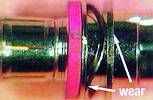
Figure 3 and Figure 4 are examples of a ControlNet failure caused by the use, and subsequent damage to, unapproved connectors. The damage had a marked impact on current flow (skin effect), which created a reflection point. This system failed six months after initial acceptance.
The connector on the cable was an unapproved BNC. It did not have sufficient spring pressure and the mechanical dimensions were less than specification. To make matters worse, it was installed in a high-vibration environment. The improper spring pressure and dimensions, combined with the extreme environmental factors, caused two wear spots on the connector (Figure 3). The abnormal wear resulted in a poor connection between the shield and the connector, which in turn created high impedance and a signal reflection point.
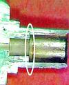
The male connector in Figure 3 was mated with the approved tap in Figure 4. The excessive vibration and improper fit caused the tap plating to wear excessively. This also created an impedance point that exceeded allowable tolerance, and a second reflection point was created.
Although poor cabling and connector installation cause a majority of network problems, it is often difficult to visually isolate the source of the problem while systems are running. Wear points and poor contact pressure are impossible to inspect without disconnecting the system. To confirm these problems, the system must be shut down (which can result in downtime). However, the signal degradation that they cause can be detected and measured during active network operation with proper test equipment.
For more information about Rockwell Automation's comprehensive suite of industrial network services, visit http://support.rockwellautomation.com//support programs
For more information contact Brett Spindler, Rockwell Automation, 011 654 9700.
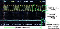
Ideal waveform
This is an example of an ideal ControlNet signal. It was created in a laboratory environment using 3000 feet of cable to simulate plant conditions, including some signal degradation. The top trace (yellow) is the incident signal, simulating a scanner module as the source. The bottom trace (blue) shows the receiving end (eg, I/O block). The traces illustrate several aspects of network operation:
* Incident signal square waves are the data transmission. Note that the peaks are even.
* There are normal, acceptable reflection points (small spikes) on the square waves that are within specification limits.
* There is a normal, calculable time delay between the start of the incident transmission and the time of receipt. The time delay is based on the characteristics of the coax cable.
* Normal 'rounding' of the waveform occurs due to inductive and capacitance characteristics of the cable.
To resolve these problems, technicians often need to recheck configurations and software, or even product integrity. Other network installation problems may not surface immediately because systems cannot be maximised during commissioning. Unfortunately, once the system is commissioned, it becomes more difficult to analyse, troubleshoot and correct these problems. If left unresolved, the problems can significantly impact long-term network integrity and performance.
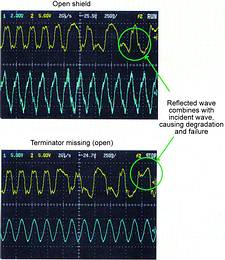
Degraded waveforms
The traces shown are extreme examples from a failed network. The trace on the top shows a network with a shield completely open. Note the effects of the reflected wave at each end. The reflected signal is combined with the incident, distorting the wave shape. The control system sees the combined incident and reflected wave. The trace on the bottom shows a network with a remote terminator missing. This also is an open system and a reflected signal is generated (although it takes a different wave shape).
In each of the examples, the reflected waves are combined with the incident signal, which causes degradation. As signal degradation increases, system retries, intermittent drops, or complete failure will occur. In plant conditions, reflections similar to the example are found, but usually to a lesser degree. Most importantly, they are typically found in combination with EMI, RFI, and grounding issues. The result: multiple sources of signal degradation.
| Tel: | +27 11 998 1000 |
| Email: | [email protected] |
| www: | www.rockwellautomation.co.za |
| Articles: | More information and articles about Rockwell Automation |


© Technews Publishing (Pty) Ltd | All Rights Reserved
 printer friendly version