

I recently wrote a Case History about control problems in a minerals extraction plant in Portugal, which was experiencing great difficulty with the control on their flotation banks. I have also written quite a few other articles in the series about control problems on this type of plant.
In some of those articles I described the importance of the individual level control in each of the cells of a bank, and how difficult it is for feedback controls to deal with changes of flow through the system. I also mentioned the necessity of trying to keep as constant a flow as possible through the bank, and that if there were changes, they should be as slow as possible to allow all the downstream level controls time to deal with them, as the dynamics of these particular level loops only allow the controllers to be tuned really slowly. Sudden changes can cause huge upsets in the levels downstream, and can easily result in permanent instability with huge cycles getting increasingly larger down the bank.
Consider the problem
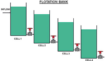
Figure 1 is a basic depiction of a small flotation bank with only four cells. In real life, the bank can contain many more cells. The level is measured in each cell and the outlet valve of the cell is used to try and keep the level constant at setpoint. (The level and other controls have not been shown in the diagram.)
One of the problems encountered in a float bank in the Portuguese plant was that every now and then the levels below one of the cells near the top of the bank would start cycling badly. The operators would then have to put the controls into manual and try and restore the level to stability and get it back to setpoint. Getting levels under control in manual can be very difficult for operators, and the plant was losing a lot in productivity and recovery due to this problem.
What the tests showed
Tests were performed on the level loop in the cell immediately upstream of the ones that were going unstable. The initial closed loop test using the existing tuning parameters showed the control seemed to be working quite well, although the tuning was very slow.
An open loop test was then performed. Part of this is shown in Figure 2. This is a typical type of open loop test that one performs on integrating processes like levels. You get the process into balance, put the controller into manual, and make steps changes on the output of the controller to get the process into ramps, either filling or emptying the vessel. This is used for problem analysis, and also to obtain the process dynamics to be able to do the tuning.
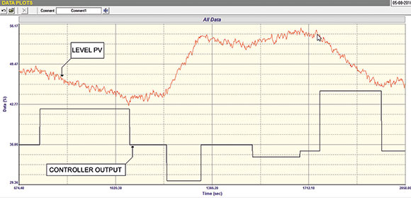
Unfortunately, identifying problems on integrating processes using this test is very limited, far more so than the equivalent tests on self regulating processes such as flows, where the test provides you with virtually all the information you need to find out what is wrong.
In this case the test looks quite good. It looks like the valve is doing what is required of it, i.e. responding to the signal from the controller and moving quickly to the correct place. However, one thing that should always be remembered when doing these tests is that one is making relatively large changes in controller output, and this comes into the positioner/valve combination as a big and fast step change, which allows the valve to get moving quickly and it hides possible small problems such as sticking that may occur when small and maybe slow changes are being sent from the controller’s output. Thus the open loop test does not always display problems that can affect the control.
The final closed loop test was then done using new tuning parameters determined from the open loop test. In this case the new tuning was approximately three times faster than the original. They were not the fastest available, but one must always make a compromise between speed, effects on the process and also downstream processes, and stability. This test is shown in Figure 3.
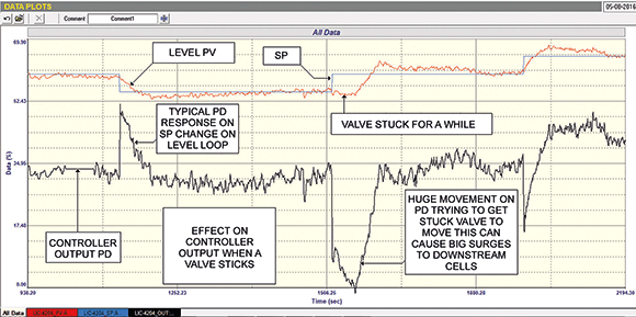
At the start of the test a small 5% setpoint step change was made downwards to lower the level. The response is quite good. Note the typical output recording from the controller tuned with P and I, and how the output comes back to the balance point.
The problem becomes evident
Once the level was stable at the new setpoint, this was moved up 5% to the original level. In this case nothing happened to the level immediately and it just stayed at the same value, and the integral action in the controller started moving the output even further down in an effort to get the level moving. Now what had happened is that the valve was sticking, and remained where it was for about 45 seconds from the time the setpoint change was made. By the time the valve started moving the controller output was at zero percent. Once the valve got through the sticking and could start moving it jumped immediately from where it was at about 38%, to virtually fully closed. This is a huge jump and caused an immediate disturbance in the output flow which of course is the input flow into the next cell downstream and this would have caused big and fast changes to its level. This in turn would result in a violent response by that cell’s controller, which in turn would cause surges in its output, and so on down the bank.
This explains why they were having this problem on the bank. It is interesting to see how just a small amount of sticking in a valve, especially on an intermittent basis can cause havoc on a control system.
Very few people realise how important it is for control valves to operate properly, and how many problems can result if they do not. Many plants, particularly in the mining industry, skimp on costs, and try and get away with inferior equipment. They always think any control problem can be solved by tuning.

Michael Brown is a specialist in control loop optimisation with many years of experience in process control instrumentation. His main activities are consulting, and teaching practical control loop analysis and optimisation. He gives training courses which can be held in clients’ plants, where students can have the added benefit of practising on live loops. His work takes him to plants all over South Africa and also to other countries. He can be contacted at Michael Brown Control Engineering cc, +27 (0)82 440 7790, [email protected], www.controlloop.co.za
| Email: | [email protected] |
| www: | www.controlloop.co.za |
| Articles: | More information and articles about Michael Brown Control Engineering |


© Technews Publishing (Pty) Ltd | All Rights Reserved
 printer friendly version