



I was recently requested to advise why a certain flow control loop in a chemical plant was cycling badly and often run in manual as nobody seemed able to tune it to work properly.
Open loop test
When we tried it in automatic it immediately started cycling, so an open loop test was performed and a section of this is shown in Figure 1. (Please note that to be able to see the figures clearly I have offset the PD (controller output signal) by +10%. The PD is actually working just above 20%.)
It can be immediately seen from the test that the valve is really horribly oversized. Measuring the process gain (movement range of PV divided by movement range of PD in percentages over the test) it shows the valve is 7-8 times oversized. This is terrible as oversized valves have the following problems associated with them:
1. Any valve problems such as hysteresis are magnified directly proportionally by the oversize factor and increase control variance by that amount. Also any cycling that can occur on the loop due to any factor, whether it is due to bad tuning or valve problems, has the amplitude of the actual cycle as seen on the PD magnified by the oversize factor. So if we had, say, a stick-slip cycle which would normally have an amplitude of about 2% with a properly sized valve, it would be about 10% with a 5 times oversized valve.
2. A very oversized valve also means that it will most likely be operating close to the seat. Now, a well-known fact is that you should not operate control valves too close to the seat. There are several reasons for this. One of the main ones is that it is possible on certain installations that the differential pressure across the valve becomes very high, and often the actuator may not have enough force to deal with it. This may cause cycling.
3. The speed of control response is largely due to the product of process gain and controller gain. Therefore, if you have an oversized valve the process gain is much higher, and it means that for stability you have to reduce the gain in the controller. Certain makes of controllers for some unknown reason have very limited low-end gains and this may cause problems.
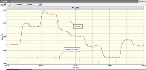
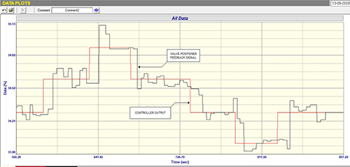
It is interesting to note in Figure 1 that although the PD is completely steady between steps, the PV seems to be ‘wavy’ and moves around quite a bit when it should also be steady. It might at first be thought that this might be due to some process problem, such as a fluctuation in the pressure behind the flow. However, the reason for this can be seen in Figure 2, in which the PD signal and the positioner’s valve position feedback signal are shown in a much magnified scale. The positioner is doing a relatively good job in keeping the valve at the PD, but it can be seen that the valve is jumping around a little. In actual fact, when measuring this movement, the valve is only travelling around in a tiny range of less than 0,5%, but because of the huge oversize this results in the PV moving around by up to 4%, which translates to large changes when translated into engineering units.
A possible reason for the valve movement is that it is working very low down and possibly the actuator has not got sufficient force to deal with the differential pressure across the valve. Another undesirable effect of this valve movement is that when in automatic with reasonable tuning, it is very easy for the loop to go into a stick-slip cycle.
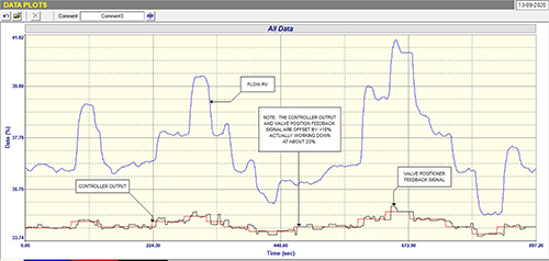
Figure 3 shows the open loop test with not only the PV and PD signals showing, but also with the signal from the positioner included. It can be clearly seen how the small amount of instability in the valve is badly affecting the PV.
Tuning the loop
I have not shown any closed loop tests, but the plant personnel had tried to tune the controller to prevent cycling. The person responsible had tuned the controller with a PB (proportional band) of 1000% and an I (integral) of 40 seconds/repeat. The 40 seconds made it extremely slow and it was still tending to cycle around.
The correct tune for this process for a maximum of a single small overshoot on an SP step change would be PB = 3000 % and I = 5 sec/repeat. (PB is the reciprocal of gain multiplied by 100 in percentage). However, the controller needed a very small gain to avoid instability. Unfortunately the particular make of controller only allows a maximum of 1000%. Luckily there is a special alternative controller module in the software that does allow one to reduce the gain considerably. Unfortunately very few people really understand all the features available in their control systems, and one of my old and often repeated ‘gripes’ about controller manufacturers is that they don’t train their clients on the intricacies of their controllers, and often their manuals are written by people with a lot of academic knowledge, but very little understanding of practical control, so that the average user cannot understand what they are trying to say. (I have given many courses to the engineers of suppliers of control systems in South Africa, and they have all said they had no idea what all the features and workings were in the control products they are responsible for – a sad situation.)
I think this example has provided a good insight into the dangers of using largely oversized valves, and into the importance of understanding practical control, and how your controllers work.
My conclusions on the problems in the loop shown previously in Case History 174
Note: Figures mentioned below, except for the last one, refer to the figures in Case History 174 (https://www.instrumentation.co.za/11645r).
Closed loop test (Figure 2):
1. Tuning is terribly slow.
2. The PV never seems to get to SP.
3. The valve is exhibiting bad sticking and slipping with the PD ramping under the I action and then finally the valve jumps way past SP.
4. On the reversal the valve is very sticky, and moves down in steps instead of smoothly.
5. The valve has fairly large hysteresis of probably about 5%, as indicated by how far the PD has to reverse to get the valve moving in the opposite direction.
Open loop test (Figure 3):
1. The 5% hysteresis is confirmed on the two reversals.
2. The valve is about two and half times oversized, which is not good.
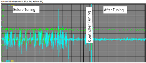
Tuning: the original tuning was very slow. The new tuning we put in worked extremely well, and managed to deal fairly well with the valve problems. The figure captioned ‘Long term trend’ in this article gives a good view of the performance before and after the exercise.
Did you manage to deduce the problems?
About Michael Brown

Michael Brown is a specialist in control loop optimisation with many years of experience in process control instrumentation. His main activities are consulting, and teaching practical control loop analysis and optimisation. He gives training courses which can be held in clients’ plants, where students can have the added benefit of practising on live loops. His work takes him to plants all over South Africa and also to other countries. He can be contacted at Michael Brown Control Engineering cc.






© Technews Publishing (Pty) Ltd | All Rights Reserved
 printer friendly version