

This article is about another loop in the same plant as I wrote about in the last Case History article (https://www.instrumentation.co.za/10641r). It is only going to be about a single flow control loop this time.
I have previously written numerous articles about problems with valves, which can be easily and clearly uncovered by looking at the flow PV through the valve, and I decided I must include this one as it so beautifully illustrates so many of these problems as they are typically encountered.
The process control metallurgists in the plant were particularly keen to try and improve the control of this loop which was quite an important flow, and which they had never ever managed to get working properly.
Closed loop test
Figure 1 is the closed loop 'as found' test that is performed with the controller in automatic, and using the existing control parameters, which were P = 0,6, and I = 45 seconds/repeat. The test shows that the control is really bad with the flow PV never really getting to set point (SP). The test was started with the SP at a particular constant value. A strange thing happened after about 3 minutes when the PV suddenly jumped upwards by about 3%. The controller did respond and carried on moving downward in a constant ramp, but the PV remained at a constant value and didn’t respond. This is almost definitely a sign that the valve was sticky.
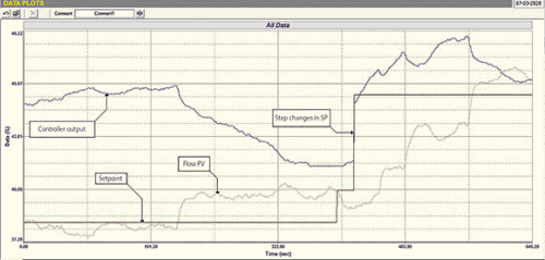
At about 6 minutes into the test, we made quite a large step up in SP and the flow did respond but slowly, showing that the tuning was very bad. It overshot SP and was starting to creep back again when we ended the test. All in all, the test shows that something is strange going on with the flow drifting around.
Open loop test
The open loop test is shown in Figure 2. (It is interesting to note that the second the controller was put in manual, the flow steadied.) The open loop test is generally always more important as it is the one that normally allows you to identify loop problems, and of course, is also the best one to use for the appropriate tuning. However, closed loop tests can also be useful at times for identifying problems, and obviously they are the ones where you can judge how good the tuning is.
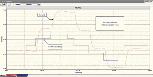
In this case, the open loop test illustrated some very classical problems:
1. Taking the ratio of the step sizes of the changes in PV to PD (controller output), it can be seen that the valve is approximately 3 times oversized. This is not good as an oversized valve magnifies all the valve problems by the oversize factor, including cycling due to valve and other problems.
2. The valve suffers from a massive hysteresis of about 8%. (Hysteresis is caused by a combination of static friction and mechanical play). The magnitude of hysteresis is determined when reversing the direction of valve movement by measuring the amount the PD has to move in the reverse direction before the valve itself also starts moving. It is generally recommended that hysteresis should be less than 1%. The main problem with hysteresis is that on a valve reversal, it can take a long time for the PD to actually get the valve to start moving again, and apart from slowing the control down and increasing variance, it can also result in other problems including closed loop cycling. (On integrating processes like level loops it will always result in a continuous cycling if one uses P+I tuning.)
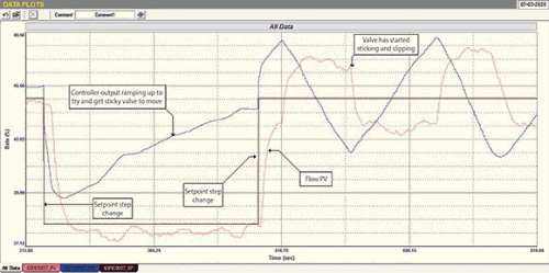 Figure 3.
3. It can be also seen that the valve overshoots when being opened, which then takes a long time for it to get back to the correct position mainly due to the hysteresis. However this does not occur in the closing direction. This might be due to some problem in the positioner tuning.
The final closed loop test is shown in Figure 3. The tuning used was P = 0,1, and I = 5,0 seconds/repeat. This is actually quite a slow tune, which is preferable when dealing with a valve that has excessive hysteresis as one would like to try and prevent overshoots as much as possible. The less the valve has to be reversed the better, as it takes so long for the controller to get the valve moving again after a reversal. The test also shows some other interesting things:
1. On the first SP step downward the PV did overshoot slightly, and it can be seen how long it took for the controller to get it back to set point due to the hysteresis. One can clearly see how the controller’s integral action was ramping up whilst the valve was sticking.
2. On the second SP step in an upwards direction the same thing happened, but this time the loop went into a closed loop stick-slip cycle.
Stick-slip cycles
Stick-slip cycles are one of the most misunderstood phenomena in feedback control. The vast majority of people believe that they are due to bad tuning. What they then do is to slow the tuning down until the cycle stops. Now, as I have said many times before, you can always stop a loop cycling by putting it in manual, which could be said to be the infinitely slowest tune. Therefore if you slow the tuning down enough, the cycle will stop, but then you are no longer really controlling, as can be seen in the as found closed loop test in Figure 1.
Figure 4 is another recording of the stick slip cycle with the new tuning parameters. This is very typical with an almost square waveform on the PV and a saw tooth waveform on the PD. What is happening is that the valve is sticking, and the PD is ramping under integral action of the controller to try and eliminate the offset. Eventually there will be enough force in the valve actuator to overcome the stiction (static friction) and the valve moves. However there is now too much energy in the actuator caused by the integral action having to move the PD so much, and the valve overshoots and then sticks again on the other side of SP. The controller now has to reverse the valve, and the whole thing starts up again in the opposite direction.
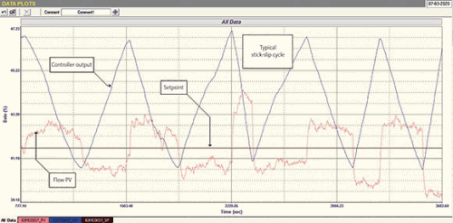
The next important thing to note in stick-slip cycles is that they are very slow. In this case, the cycle has a period of close to 3 minutes: if a flow loop cycles due to unstable tuning it will cycle close to the ultimate period of the loop, which is the loop’s natural resonant frequency. In the case of this particular flow loop, the ultimate period is about 14 seconds (figure taken from the frequency analyses done by the Protuner from the open loop test). Therefore the loop’s cycle is about 13 times slower that it would have cycled due to unstable tuning. Also, a cycle due to unstable tuning is more sinusoidal in nature, and does not have square and saw-tooth appearances like this.
All in all this is really a wonderful illustrative example of the typical valve problems frequently encountered on control loops.
About Michael Brown

Michael Brown is a specialist in control loop optimisation with many years of experience in process control instrumentation. His main activities are consulting, and teaching practical control loop analysis and optimisation. He gives training courses which can be held in clients’ plants, where students can have the added benefit of practising on live loops. His work takes him to plants all over South Africa and also to other countries.
| Email: | [email protected] |
| www: | www.controlloop.co.za |
| Articles: | More information and articles about Michael Brown Control Engineering |


© Technews Publishing (Pty) Ltd | All Rights Reserved
 printer friendly version