As mentioned in an earlier article in this Loop signature series, the integral or I term in the controller is a brilliant thing. It is an extremely elegant and simple solution for eliminating offset in control. However, like everything else in this world, virtually everything good has its bad side as well. In the case of the I term, its bad feature is that it never gives up trying to get rid of offset, even if it cannot be eliminated.
Many of our control problems stem from the integral continuously working to try and eliminate offset. Some examples of these are stick-slip cycling on self-regulating processes and continuous cycling on integrating processes with hysteresis on the valve, which have already been discussed in earlier articles. In addition, another problem can arise from the same cause, and this is known as integral or reset windup.
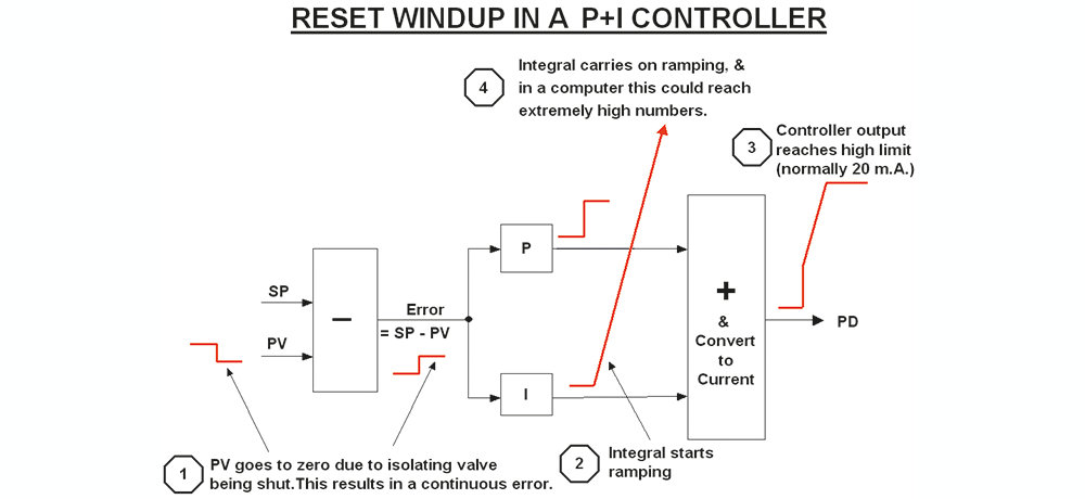
Integral windup occurs when a continuous error exists which cannot be eliminated. To take an example, imagine that an isolating valve in series with the control valve is closed, and the controller is left in automatic. At this point, let us imagine that the process variable (PV) goes to zero. The integrator in the controller will immediately start integrating to try and eliminate the error. This will result in the PD (controller’s output) increasing at the ramp rate of the integrator. As the error cannot be reduced, this will continue until eventually the PD reaches a maximum limit (normally set to 20 mA in most controllers).
However it must be remembered that in theory, the integrator’s output will continue to carry on ramping for as long as the error exists. In reality, in the old days of pneumatic and electronic analogue controllers, this could only continue until a physical limit such as air supply pressure, or a bus voltage, was reached. At this point it was said that the integrator was ‘saturated’ or fully ‘wound up’.
The situation is different in a digital computer. The integral is now not a voltage or pressure, but a number, and modern computers can deal with extraordinarily high numbers. Therefore, unless the controller manufacturer does something about it, the integrator could carry on virtually until the output reaches a value close to infinity. This is illustrated in Figure 1.
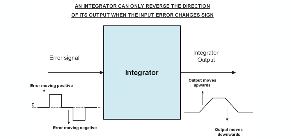
Eventually when the process is restarted, and the isolating valve reopened, fluid will flow through the fully open control valve. The PV will then start rising towards setpoint. However, due to the nature of an integrator, the PD cannot start reducing, and hence the control valve cannot start closing, before setpoint is reached. Figure 2 helps explain this. Essentially the integrator’s output cannot be reduced until the error signal on its input changes sign. This is because the integrator’s output will always rise as long as any positive error exists. If the error reduces to zero, the integrator’s output then remains constant. It can only start moving down after a negative error signal occurs. This means that the integrator can only start responding again once the PV has moved through the setpoint.
If the integrator has wound up, it means that it may take a long while for the integrator’s output to drop far enough to allow the PD to start moving down again, and at that point it would allow the control valve to also start closing. By this time an enormous process overshoot could have occurred.
To overcome this problem, most of the controller manufacturers incorporate a strategy, often referred to as ‘anti-reset windup’, to prevent the integral from winding up. The method used varies from manufacturer to manufacturer, but most of them ‘freeze’ the integral unit’s operation when the PD reaches low or high limits (generally at 4 and 20 mA.). At this point the output of the integrator remains constant at the last calculated value, and does not carry on winding up.
This method of anti-reset windup still does not prevent overshoots, as again the integrator cannot start decreasing until the error actually reverses at the point the PV reaches setpoint. However the overshoots will be much smaller than they would have been if no anti-reset windup had been employed.
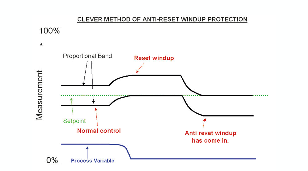
Some of the manufacturers employ more sophisticated methods of anti-reset windup, which can limit the overshoot even more. Typically one of them works as follows (refer to Figure 3, for a graphical description).
When a controller winds up, it effectively forces the proportional band fully away from the setpoint, in fact all the way to the far side of the setpoint. The method used in this particular case is that when the controller detects windup, it artificially forces the proportional band to move back in the opposite direction to the windup, so that it’s other side is now forced down against the setpoint. In this manner the controller will start reacting as soon as the PV re-enters the proportional band after the control is coming back to normal. Effectively the method reduces the value of the integral to enable this procedure to take effect.
External anti-rest windup
There are certain other situations where it is also important to be able to freeze the integral from an external signal. This is sometimes known as ‘external anti-reset’ windup. Two cases in particular are where more than one controller is connected to the same valve.
The first of these is ‘over-ride’ or ‘selective’ control systems. This control strategy is frequently used for turbo-compressor anti-surge control. Various parameters like output pressure and flow can reach a value where a surge can occur through the compressor. At these limiting values, the output of the compressor needs venting. A controller is provided for each limiting parameter, the outputs of which generally pass to the vent valve via a high or low signal selector. Whichever controller’s output is the highest or lowest respectively takes over the control of the valve. The other controllers will then tend to wind up. It is therefore essential that their integrals be prevented from doing this by freezing them at their last values.
The second case is in cascade control systems, which were discussed in the previous Loop Signature article. Remember the master control loop is generally at least 10 times slower than the slave loop. If the slave controller’s output reaches a high limit, at which point its own anti-reset wind-up protection will come in to freeze its integral, then it is very important to also freeze the master controller’s integral to prevent it from integrating further. Huge overshoots can occur if this is not done.
It should be noted that most of the DCS systems do take this into account and provide such a feature. Unfortunately very few PLC manufacturers seem to be aware of this, and seldom make provision for external anti-reset windup.
About Michael Brown

Michael Brown is a specialist in control loop optimisation, with many years of experience in process control instrumentation. His main activities are consulting and teaching practical control loop analysis and optimisation. He now presents courses and performs optimisation over the internet.
His work has taken him to plants all over South Africa and also to other countries. He can be contacted at: Michael Brown Control Engineering CC,
| Email: | [email protected] |
| www: | www.controlloop.co.za |
| Articles: | More information and articles about Michael Brown Control Engineering |


© Technews Publishing (Pty) Ltd | All Rights Reserved
 printer friendly version