Case history 186: Don’t always trust valve position feedback signals
March 2023Editor's Choice
PLCs, DCSs & Controllers
I recently encountered an interesting problem in a minerals recovery processing plant. The loop in question was a gas flow control to a burner and was considered very important for the process temperature control. The operators reported that the loop cycled badly in automatic, and was very difficult to control manually. The C&I technicians had tried all sorts of tunings without any improvement.
They included this loop in a series of optimisation tests we were doing as part of the practical we held after they had finished the classroom part of my basic control course. They said they knew that valve problems often cause problems for control but that this loop had a valve position feedback signal on it and the feedback signal closely followed the controller output signal so they were pretty sure it wasn’t the cause of the problem.
The first test we normally carry out is a Closed Loop As Found test and we recorded how the loop responded to setpoint (SP) changes in automatic with the original existing tuning parameters. However, as reported, the loop cycled badly.
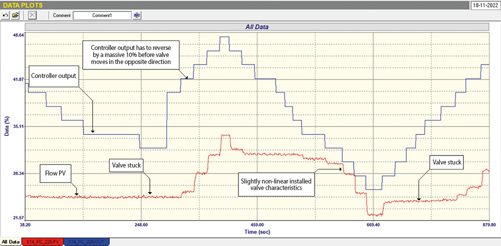
The second test was an Open Loop test where the controller is placed in manual, and various steps are then made on the PD (controller output). Part of this test is shown in Figure 1. Unfortunately we did not record the valve position feedback signal. It can be immediately seen that there was in fact a huge valve problem as the valve was not only apparently sticking in places but also had huge ‘almost hysteresis’ of over 10%. I say ‘almost hysteresis’ because it did move a little on most reversals and then stuck whilst the PD had to move a further 10% before the valve moved again. This was the major reason for the cycling.
The question is why the valve feedback signal followed the PD so closely. The answer is, and this is something every control practitioner should be aware of, valve position feedback signals generally do not track the actual valve position, but track the position of the actuator. Now depending on the type of valve and actuator, there are often various linkages joining the two. In this case the valve was a butterfly valve, which is a rotary valve. The actuator was a spring and diaphragm type which has a linear action. To convert the linear action to a rotary action, manufacturers employ various techniques, typically geartrains. Therefore the hysteresis and/or apparent stickiness may actually be due to play in the linkages.
On the steps where the valve, and hence the flow PV, did follow the PD, we were able to see that there was a slight non-linear installed characteristic in the valve, and we were able to establish the process dynamics to allow us to get good tuning parameters. The original tuning parameters were actually too fast and were contributing to the cycling, so it was not only due to the valve problem, and the tuning was also causing instability.
Final Closed Loop test with the new parameters is shown in Figure 2 and is interesting. On the SP step down it can be seen how the valve started moving and then stuck, and the PD then integrated down well over 10% before the valve could move again and bring the PV back to SP. On the SP step up the valve initially didn’t move at all until the PD had integrated up the same amount, and then it moved to get the PV to SP.
This is another example of how important it is to analyse a loop before tuning and to be aware of the various problems that can exist. As I have said many times in the past, the old adage that tuning can solve all problems is nonsense. I have seen the same problem of slippage in the valve linkages many times in the past, and it somis ething that not many C&I; practitioners seem to be aware of.
About Michael Brown
Michael Brown.
Michael Brown is a specialist in control loop optimisation, with many years of experience in process control instrumentation. His main activities are consulting and teaching practical control loop analysis and optimisation. He now presents courses and performs optimisation over the internet.
His work has taken him to plants all over South Africa and also to other countries. He can be contacted at: Michael Brown Control Engineering CC, +27 82 440 7790
Yokogawa digital plant to accelerate green hydrogen revolution Yokogawa South Africa
Editor's Choice Electrical Power & Protection IT in Manufacturing
Yokogawa explains how a digital plant approach and autonomous operations can integrate the full green hydrogen value chain, from renewable power generation to end-use applications, and why digitalisation and system integration are central to making green hydrogen viable in South Africa.
Read more...Next-generation autonomous mobile robots from Omron Robotics Omron Electronics
Editor's Choice
The new LD-150 and LD-300 autonomous mobile robots from Omron Robotics offer higher payload capacity and advanced navigation in a compact footprint, with wireless inductive charging and fleet management integration to support high-throughput material transport in demanding production environments.
Read more...DriveRadar and AI provide smarter maintenance in tough mining conditions SEW-EURODRIVE
Editor's Choice
SEW-EURODRIVE’s DriveRadar system has already embedded AI into predictive maintenance for African mining operations. Jonathan McKey explains how the system monitors external conditions, interprets data and tells operators exactly how much longer a drive can run safely before intervention becomes necessary.
Read more...XTS for highly efficient end-of-line packaging of beverage bottles Beckhoff Automation
Editor's Choice
Italian machine builder Clevertech used Beckhoff’s XTS linear transport system to help a Dutch distillery double its bottle packaging throughput to 225 bottles per minute while cutting format changeover times from 30 minutes to just seven.
Read more...Loop signature Part 2-5: Interactive control systems Michael Brown Control Engineering
Fieldbus & Industrial Networking
Feedforward control was explained in the previous loop signature articles. One of the examples used was feedforward control of load changes on a heat exchanger when variations occurred in the flow of the process fluid through the exchanger.
Read more...Motion control for flight simulators Beckhoff Automation
Editor's Choice Motion Control & Drives
Turkish specialist, SANLAB is a leader in motion platforms and simulation technologies. At the heart of these platforms are application-specific servo drives, servomotors and industrial PCs for real-time control, which are supplied by Beckhoff.
Read more...Conductivity sensing as a cornerstone of South Africa’s water smart industry ifm - South Africa
Editor's Choice Sensors & Transducers
South Africa’s engineers operate at the intersection of resource constraint and industrial ambition. Few parameters illustrate this balancing act as clearly as water quality. Whether in municipal treatment works, food and beverage plants or mining operations, the ability to measure water quality accurately and continuously has become non-negotiable.
While every effort has been made to ensure the accuracy of the information contained herein, the publisher and its agents cannot be held responsible for any errors contained, or any loss incurred as a result. Articles published do not necessarily reflect the views of the publishers. The editor reserves the right to alter or cut copy. Articles submitted are deemed to have been cleared for publication. Advertisements and company contact details are published as provided by the advertiser. Technews Publishing (Pty) Ltd cannot be held responsible for the accuracy or veracity of supplied material.


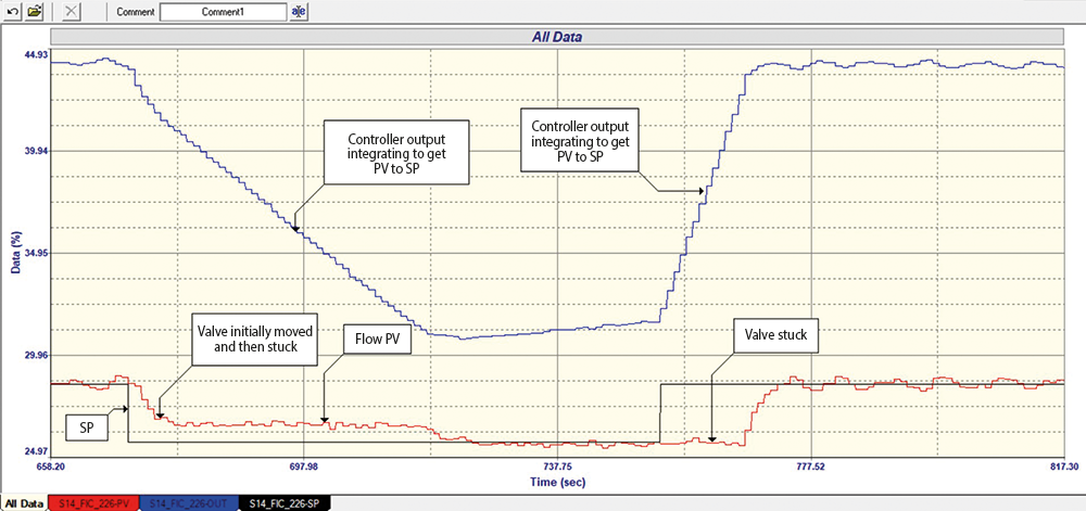 Figure 2. Final Closed Loop test


 printer friendly version