

A simple controller complete with all three parameters, P, I and D is shown in Figure 1. As shown in the figure, if a setpoint step change was made, an error signal would appear on the output of the subtraction block. Alternatively an identical error signal would occur if the PV changed in a step of equal magnitude, but in the opposite direction. (A change in PV due to an effect in the process not caused by the controller is known as a load change.) The step in error would then go through the controller and would be acted on simultaneously by all three
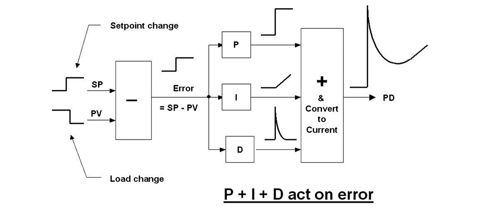 Figure 1. The full PID controller.
Electronic analog PID controllers appeared on the market in the 1960s. They offered considerable advantages, particularly flexibility, as opposed to the old pneumatic controllers. At that time people were still trying hard to make feedback control systems operate better. Bearing in mind that the vast majority of controllers were used in continuous process plants, the manufacturers realised that, in general, the type of response as seen in the figure which causes the valve to kick open (or shut as the case may be) would not be desirable in most situations on a working plant. Typically such plants take a long time to start up and get running optimally in steady state conditions. The last thing process people want on most loops when running in steady state is for a valve to suddenly kick wide open. It could cause a plant trip, or it could initiate large disturbances to processes downstream.
When I begin my courses or give presentations on regulatory control, I normally start off by mentioning that, in general, I find about 85% of the loops I examine in plants worldwide are completely detuned. Many process engineers will state that they are quite happy with this. I have been told many times by senior process people that they would far rather have their loops detuned than running fast and bumping the plant around. Are they correct or incorrect? The same people will often ask me to tune a critical loop as well as possible, as its operation is critical to further process downstream, and then they will add that it must not be tuned so fast that it could cause bumps. So in the same breath they are effectively saying the loop must be tuned fast, and then they are saying it should be tuned slowly.
If people want the controllers detuned then why bother having them in the first place? Why are regulatory controls needed at all on continuous process plants?
A world-leading American control engineer answered this question recently in an article where he stated that the purpose of the regulatory controls in a continuous process plant is to minimise variance throughout all stages of production. What he means by this is that when such a plant is running at steady state conditions, the regulatory controls are there to keep all the various processes as close to setpoint as possible under all conditions of change, so that minimum variance is achieved.
What changes can occur when plants run at steady state? Firstly load changes can and often do occur. Such changes are seldom very fast and ‘steppy‘, but normally occur quite slowly. Typical examples are ambient temperature changes affecting plant exposed to the outside environment, like petrochemical refineries. Such plants typically often swing quite badly with day-night temperature variations. Slow load changes like this will not cause a big kick on the controller’s output if it is tuned fast. However the fast tuning should be able to catch the changes and minimise deviations from setpoint.
The second type of changes that will be encountered on continuous process plants are setpoint changes that operators make whilst optimising the plant. Setpoint changes are generally steps. These will result in controller output kicks if full PID control is employed. In most cases in a plant, it is not actually necessary to have a fast response to a setpoint change. A slower response is generally quite acceptable.
One can summarise the above requirements with two very important premises that state:
1. Fast control is required for load changes.
2. Slow control is required for setpoint changes.
Please note that these premises are generalised, but they do apply to the vast majority of control loops found in continuous process plants. There are of course some loops that do require a fast response on setpoint changes. Examples would be cascade slave loops, or loops where their setpoints are being set from some higher level control system.
To achieve the above differences in response, you could use ramps on setpoints. However this is seldom done. The controller designers back in the 1960s came up with a better idea. They reconfigured the controller as shown in Figure 2.
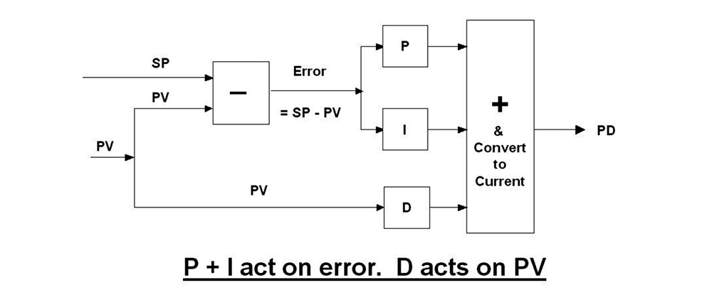 Figure 2. The PI-D controller.
In this new configuration it can be seen that the D term is now only on the PV signal and is not acted on at all by the error signal. If we have a load change, the D term acts only on the PV signal, whilst the P and I terms act on the error signal, resulting in a full P+I+D response. However on setpoint changes, only P+I acts on the error signal. There is no D response at all until the PV starts moving in response to the change in the PD (controller output signal), and this D contribution to the response is relatively small.
This configuration virtually became a standard at that time. Nearly every controller manufacturer used it. Even today it is still generally the default configuration on most industrial controllers. This is not a bad thing from the control point of view in most cases. I am personally only aware of one particular type of process where it is really desirable to use the D term on a setpoint change.
However of far more importance, and what no one, including most controller manufacturers seem to be aware of, is that this configuration in practice actually prohibits the use of the D term completely, even if you should wish to use it in situations where it would help deal with load changes. The reason is that this configuration makes it almost impossible to test the tuning of the D term on the controller.
This is because to test tuning one must watch how the controller responds to setpoint changes. You can play with the D ‘knob‘ until you are blue in the face, but you will not be able to see the true effect of its action whilst making setpoint changes. The only way to really be able to check it is by inducing step load changes, and this is usually very difficult to do in practice.
Probably the main reason why the D term is so seldom used is because most controllers have this configuration as their default, and hence one cannot tune in the D term. I personally would never ever consider purchasing a controller that did not allow me to change back to a full P+I+D response on setpoint change in order to allow me to perform tuning tests. Remember that the D term can be very effective when used in the right processes where it can operate effectively − see earlier loop signature articles dealing with the D term.
When controllers were written into computers in the 1980s, some manufacturers took the configuration one step further to slow down the response on setpoint changes even more. In many instances, particularly on integrating processes, you can have a large proportional gain in the controller. Thus if there is a high P gain in the controller, setpoint changes can also cause a big kick on the output. To prevent this happening, a new configuration was drawn up, so that the P and the D terms are both removed from the error and effectively put on the PV signal. Such a configuration is shown in Figure 3. The drawing is purely representational. In reality, the operation is performed by the use of a mathematical formula, as you cannot have the P acting directly on the PV signal.
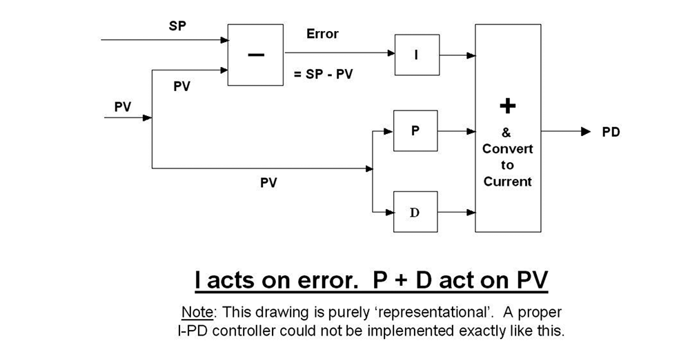 Figure 3. The I-PD controller.
This controller really does give nice slow response on setpoint changes, but the practical effects of it are even more dramatic. A controller with this configuration cannot be tuned at all. This is because the one term you must get right when tuning is the P term. You can again play around on this controller making setpoint changes and adjusting the P term as much as you like, but you will not get any P response. The only change on the PD will be caused by the integral response.
You would think that most people would be aware of this, and that the manufacturers would put a big note in their manuals explaining that this configuration cannot be used when tuning. However, in reality, I have never seen such a note in a manufacturer’s manual. I have been into many plants where the control system has an integral only response on setpoint change as the default configuration. In nearly every such plant no one was aware of the configuration, and as a result the tuning in these plants was shockingly bad.
Apart from terrible control, this lack of understanding has resulted in direct financial loss in at least one plant I visited. This was a pharmaceutical manufacturer in the UK that had chosen only P+I action on setpoint response for use on batch reactors. This is a case where the D response on setpoint change is essential. It can literally speed up the response on a setpoint change by a factor of four. After testing a setpoint change with a full PID response, and on observing how much faster the process reacted, the production manager estimated that they could have increased production though the plant by approximately 14 million pounds sterling per annum. Unfortunately, the various drug authorities of countries to which the pharmaceutical companies distributed their products insisted that the manufacturing processes be sealed once they had been accepted, and no changes were permitted.
It is very difficult and expensive to get changes authorised at later dates.
This is a very good example of why it is so important for users to understand fully how their controllers operate, and what options are available. As said in an earlier loop signature, it is essential that you fully understand your controller if you wish to successfully optimise your plant.
About Michael Brown

Michael Brown is a specialist in control loop optimisation, with many years of experience in process control instrumentation. His main activities are consulting and teaching practical control loop analysis and optimisation. He now presents courses and performs optimisation over the internet. His work has taken him to plants all over South Africa and also to other countries. He can be contacted at: Michael Brown Control Engineering CC,
| Email: | [email protected] |
| www: | www.controlloop.co.za |
| Articles: | More information and articles about Michael Brown Control Engineering |


© Technews Publishing (Pty) Ltd | All Rights Reserved
 printer friendly version