

Desuperheaters are an important element in boilers, and are used to reduce the temperature of superheated steam to a desired value. The control of desuperheaters is extremely important.
There are often quite complex temperature-to-temperature cascade control loops used in desuperheating control, and the final output steam temperature is controlled by adding spray water into the superheated steam. The temperature control of the final temperature is performed using a normal feedback (PID) controller.
On a couple of occasions (one in a large power station in the UK and another in a petrochemical refinery in South Africa) I have found that the people who implemented the control systems fed the output of the desuperheater temperature controller directly to the desuperheater spray water control valve. On both occasions I found huge problems occurring with the temperature control after the valve had aged.
Essentially, the output of the controller (PD) is ‘demanding’ that a certain quantity of water be fed into the desuperheater to satisfy the requirements of the controller as calculated by its PID algorithm, and thus ensure that the temperature process variable (PV) is kept as close as possible to setpoint (SP) with minimum variance at all times.
When the PD sends the signal directly to the valve, it is actually ‘asking’ the valve to move to a certain position. If the valve is sized and set up correctly and if it has no problems, then the correct volume of water should in fact be fed into the desuperheater. In reality, an average of 75% of valves exhibit problems of many different types, which may get worse as they age. Therefore, if they do have problems, or have not been set up correctly, they might not feed the correct quantity of water into the steam, as ‘directed’ by the temperature controller.
Another important thing to note is that one of the major limitations of feedback control is that you can only tune a controller to control a process as fast as the dynamic response of the process will allow. This, very broadly, means that fast processes (like flow) can be tuned with fast control, but slow processes (like most temperatures) can only be tuned with slow control. If you try and speed up the response of the control system to react any faster to changes such as SP changes or load disturbances (where the PV moves away from SP), then the loop starts cycling.
It is therefore very important that the equipment in the loop used on slow processes works well and without problems, because if the controller has to try and correct for errors caused by equipment like valves, as well as having to respond to changes in error (difference between SP and PV), then the control becomes very difficult and it may take an extremely long time for the controller to get the PV to the correct value.
To overcome this problem, in my opinion it is mandatory to use a flow control on the valve, with its SP coming from the PD (output) of the temperature controller (this is known as a cascade secondary flow control). The temperature control is now actually asking the flow controller to ensure that the process receives the exact volume of water that is required to meet the requirements of the temperature control.
The speed of the flow loop control is much faster than the temperature control, so it can quickly ensure that the valve does in fact deliver the correct amount of water into the desuperheater, and as a result the temperature process is not affected by any of the valve problems. This works brilliantly and I have helped plants achieve excellent control on slow processes with valves that are not working very well.
The first example in this article is taken from a desuperheater temperature controller that was sending its PD signal directly to the valve, and where the temperature control was so bad that the operators were running the loop in manual, with very poor results. Luckily there was a flowmeter in series with the valve, so we could test the valve performance.
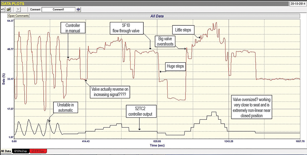
Figure 1 shows the test done on this valve. The test shows how the flow through the valve behaved, with the signal coming directly from the PD of the temperature controller. The test showed some remarkable faults:
1.The valve is working very close to ‘seat’ at around 5% of opening. This means that the valve is hugely oversized. A well-known general rule is that, under normal load conditions, a valve should never work too close to seat, and as a guideline it is suggested that it should be above 20%. The reasons are that manufacturers cannot machine a valve plug to give really good linearity when close to seat, and also there might be huge forces on the plug if the differential pressure across the valve increases as the valve closes, which can cause uncontrollable cycling.
2. At the start of the test, the controller was in automatic, and it can be seen that a continuous cycle was in fact occurring.
3. The controller was then switched into manual and a series of step changes made on the PD of the controller. These showed:
a) In some places the valve actually moved in the opposite direction to the direction of the PD step.
b) On many steps the valve had huge overshoots.
c) The valve displayed seriously bad installed non-linearity.
d) The valve displayed extreme stickiness at times.
It was concluded that the valve could not provide proper control for the desuperheater temperature, and should be replaced. It was also recommended that, until this could be done, the plant should install a cascade flow control loop, which should be able to keep the flow more or less in the right place to at least achieve some semblance of temperature control.
To illustrate how this could work, the second example in this article is of a similar control on another desuperheater where the valve had serious problems, but they were still getting good temperature control on the desuperheater because they had used a cascade flow control with it.
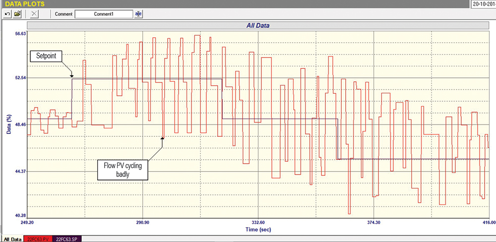
Figure 2 shows a closed-loop test on the cascade flow loop, and it can be seen that the loop is in a continuous cycle. Now, although many people always attribute closed-loop cycling to bad tuning, there are also many other reasons why it may be cycling.

Figure 3 shows the open-loop test on the loop. Two major problems are immediately seen:
1. The valve is oversized by approximately four times, which can be seen from the relative step sizes in PV versus PD. It must be remembered that oversized valves multiply all the valve problems by the oversize factor.
2. On each valve reversal, the PV overshoots quite considerably. This is known as negative hysteresis, which can be a very bad problem as it often causes uncontrollable instability in the loop. It is caused by either insufficient power in the actuator to overcome the static friction properly, or else by positioner problems.
This is a wonderful example of how the use of a cascade flow control still allowed excellent control of the primary temperature control loop to be achieved, in spite of a valve with severe problems. If the output of the temperature controller had been fed directly to the valve, there is no way that proper temperature control could have been attained.
About Michael Brown
Michael Brown is a specialist in control loop optimisation, with many years of experience in process control instrumentation. His main activities are consulting, and teaching practical control loop analysis and optimisation. He now presents courses and performs optimisation over the internet.
His work has taken him to plants all over South Africa and also to other countries. He can be contacted at: Michael Brown Control Engineering CC,
| Email: | [email protected] |
| www: | www.controlloop.co.za |
| Articles: | More information and articles about Michael Brown Control Engineering |


© Technews Publishing (Pty) Ltd | All Rights Reserved
 printer friendly version