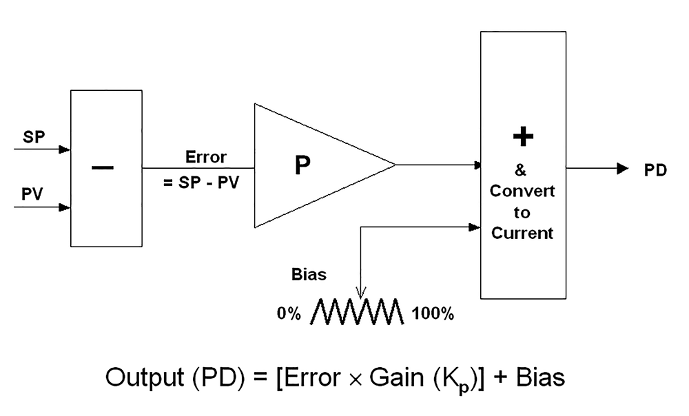
Figure 1 shows a simplified P-only controller. The P term may be considered as a pure amplifier that multiplies the input error signal by whatever gain (Kp) is set in the controller to produce the controller’s output signal (PD). The bias allows the output to be manually adjusted either up or down between 50% and 100%.
Figure 2 shows a recording of a test on a P-only controller with
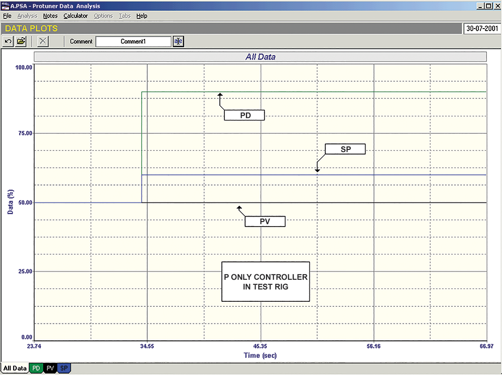 Figure 2. Test data plot of a P-only controller with Kp = 4.
As there are no standards for PID controllers, manufacturers use various units for the P term. Probably the most common is ‘gain’, which, as mentioned above, is the amplifying factor and is defined as the size of the output step divided by the size of the input step.
Another term used by quite a few manufacturers is ‘proportional band’. The relationship between gain and proportional band is:
Proportional Band = (1/Gain) x 100%
Proportional band is sometimes a useful concept to aid one in explaining controller responses, as it may be considered as a graphical representation of the control range. This is illustrated in Figure 3, where a gain of 2 has been entered in a P-only controller. The proportional band works out at 100/2 = 50%. This can be drawn as a band of 50% width lying around the setpoint. Note that the band need not be equidistant around the setpoint, but can in fact move around it. However, in ordinary controllers the band can normally never move away from the setpoint (the position where the setpoint lies within the band is in fact set by the value of the bias).
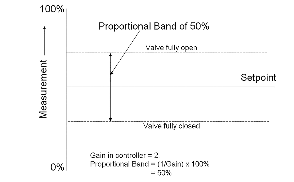 Figure 3. The proportional band is a graphical representation of the control range.
Assume that, at a particular moment in time, the PV value was sitting on the bottom edge of the proportional band. This would mean that at that time the valve would be at one of its extremities, either fully open or fully closed. If the measurement were then to move up to the top of the proportional band, the valve would have moved through its range to the opposite extremity. Thus, the proportional band represents the control range, as control can only be achievable between the two valve extremities.
This leads to an interesting thought. In the first article in this loop signature series (see https://www.instrumentation.co.za/10379r), it was mentioned that control performance or variance is a measure of error, effectively totalised over a period of time. If we were able to put more gain into a controller and make the proportional band narrower, then it is feasible to believe that the variance would improve, as errors should be smaller and in a narrower proportional band. Therefore, the smaller the band, the better the variance, provided we could in fact achieve control within that band.
Taking this concept to a ridiculous extreme, we could speculate that if we were to put an infinite gain into the controller and make the proportional band infinitely small (i.e., zero), then we should have zero variance, as there should then be no control error. Infinite gain is of course on/off control and as we know, on/off control is in fact in a continuous cycle, either switching the final control element fully on or off, as the PV rises and falls through the setpoint. This results in very poor variance.
In reality, as the gain is increased in the controller, the loop will eventually start reacting to changes in setpoint or load with a cyclical response and this will worsen as the gain is increased. Therefore, for minimum variance, there is a balance between the amount of gain we can insert in a controller and the amount of cycling that we would be prepared to tolerate in any particular control loop. The actual limit in practice would be where the gain in the controller would give rise to a quarter-damped amplitude response on a step change in setpoint.
To explore the limitations inherent in a P-only controller, take the practical case of such a controller that is often still encountered in level controls in plants – the ball valve. The ball valve and level process make up a complete feedback control loop, with the ball as the measuring element. The arm connecting the ball to the valve is the proportional control mechanism and the valve is the final control element.
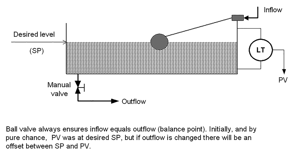 Figure 4. Ball valve used with a P-only controller.
Imagine the system illustrated in Figure 4 is being used for controlling the level in the reservoir feeding water to our plant. When we examine the system, let us imagine that we find that the inflow and outflow are equal. The level is therefore constant at some particular point; let us call this point our desired level, the setpoint. We then proceed to perform a little experiment and open the manual valve controlling the flow of water to our plant by 10%. As the valve opens, the flow increases and the level starts dropping. As it does so, the ball drops with it and opens up its valve, which in turn increases the flow of inlet water.
Eventually the inflow will equal the outflow, at which point the level stops dropping and will remain constant. The control system is now in equilibrium and the level will remain at the new value, as long as no further changes are made to the manual valve.
The level is again under control, but is no longer at setpoint, and we say that we are now controlling the level with an ‘offset’. Offset is the main drawback to P-only control. There is nothing in a P-only controller that can do anything to permanently eliminate the offset. For practical purposes, one can generally assume that a P-only control system will almost definitely control with offset at some stage or another.
In certain instances, one can tolerate a certain amount of offset, however, the majority of control loops are there to keep the process at the setpoint. The best one can do with a P-only controller is to minimise offset. This can be achieved in two ways.
Firstly, if the controller gain is increased, the offset will decrease proportionally.
Secondly, one can bring the process to the setpoint by adjusting the valve position manually. In the example of the ball valve above, one could physically bend up the arm between the ball and the valve to allow the level to come back up to the setpoint. In a real controller, the same effect can be achieved by adjusting the bias. This adjustment is often called ‘manual reset’. The problem with manual reset is that if you had reset the offset at a particular point in time, then when changes occurred in the process again, another offset would result. In practice, manual reset is used only for initially setting up P-only control systems.
In the real world of industrial process control, P-only control should be used only on processes that are tuned with a large P gain value. It would generally be impossible to use it where the P value is small, as large offsets could result. Therefore, one normally only finds P-only controllers on integrating loops such as level controls where high controller P gain is normal.
Integrating loops are in actual fact better without the I term in the controller. There are two reasons for this. The first is that, as mentioned in previous articles, any hysteresis on a valve in an integrating process that is controlled with P+I control will result in continuous cycling. The second reason is that the I term introduces a second integral term into the combined loop process transfer function and prevents perfect pole cancellation tuning from being achieved. Therefore, the only reason one should technically ever use the I term in the controller on an integrating process is if the possible offset is unacceptable. However, in reality, most people don’t like processes being controlled with offset, even if it is actually acceptable and as a result one finds that the I term is used on most integrating processes.
About Michael Brown
 Michael Brown.
Michael Brown is a specialist in control loop optimisation, with many years of experience in process control instrumentation. His main activities are consulting and teaching practical control loop analysis and optimisation. He now presents courses and performs optimisation over the Internet.
His work has taken him to plants all over South Africa and also to other countries. He can be contacted at: Michael Brown Control Engineering CC,
| Email: | [email protected] |
| www: | www.controlloop.co.za |
| Articles: | More information and articles about Michael Brown Control Engineering |


© Technews Publishing (Pty) Ltd | All Rights Reserved
 printer friendly version