The example given in this article is about solving the control problems in a critical flow loop supplying hydrogen gas to a reactor in a smelter plant. The complete production of the reactor plant and hence the smelter, was reliant on good performance of this loop, which is a secondary cascade control to the hydrogen pressure input to the reactor.
The operators were really keen on us getting this loop to perform properly. They complained that it never actually got to set-point when it was in automatic and that the control reacted terribly slowly if there was a load disturbance or set-point change. As a result they mostly ran it in manual.
On examining the controller’s setup it was immediately seen that for some reason there was a 1% dead band on the control and secondly, there was a 6 s filter on the PV pressure signal in the PLC.
Dead band and filter use in control loops
A dead band on most controllers usually consists of a band placed symmetrically around the SP – if the PV is within this band there is no control action. Now, the real purpose of the dead band is for use with certain types of electric actuators. These devices incorporate a reversible electric motor, which can run in both directions so as to open or close the valve. The problem with these is that when the PV is at SP, the motor switches backwards and forwards continuously as the PV moves up and down, which is normal even with only a little noise on the PV signal. (We define noise as a random fluctuation in the PV signal and it is always present on real life variables. It is caused by various factors such as turbulence in a flow, ripples on the surface of a vessel on level measurement, or something in the measuring system.)
A dead band is not ideal as it stops control action within the band and I have often found dead bands set far too wide, some as high as 20% or more. There are also some other problems that can occur with dead bands if the control system is not implemented correctly, which can result in continuous cycling from one side of the band to the other. However, the one case where they are necessary is on the type of electric actuator discussed above.
I have written a lot about the problems with noise in the past and have shown that noise is seldom a problem as regards effects on the control of the process. However, because of a general lack of understanding by plant personnel as to the effects of noise on control and because of the ease of eliminating it by using filters, which are easy to implement on digital control systems, it has become common to eliminate it completely. However, few people realise that the use of filters can introduce other problems that can badly affect and cause deterioration in control performance.
The majority of control loops do not use electric actuators, but incorporate the old tried and tested pneumatic variety. These have natural lags in them and act as a dampener, so most noise, which is generally at a relatively high frequency, does not cause a problem. However, sometimes people try and eliminate the effects of noise by incorporating the dead band feature into the control, as they did in this case, on a loop which had a standard pneumatic actuator. (In this case they also incorporated a filter – really trying to ensure that the noise wouldn’t cause a problem.)
Back to the example of the hydrogen flow control
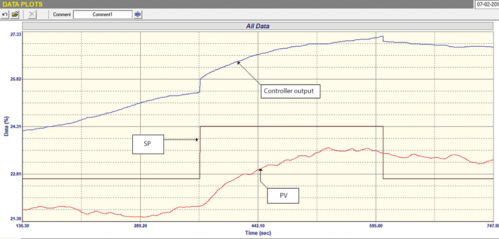
Figure 1 shows a closed loop ‘as found’ test, which is a recording of the control responses to step set-point changes, without changing anything like dead bands, filters or tuning parameters. It can be seen that:
1. The PV never got to SP because of the dead band.
2. The response was unbelievably slow on a SP change. This was due to the filter and also to terribly bad tuning, which was P = 0,25 and I = 24 s/repeat.
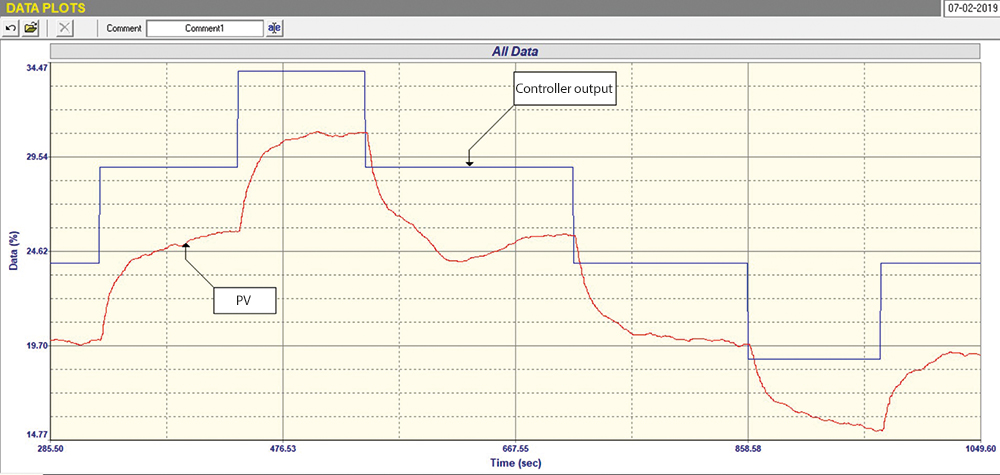
Figure 2 shows the open loop test, where the controller is in manual and step changes are being made on the PD (controller output). The 6 s filter was removed from inside the control system in the PLC. However, from the response and based on experience, it looks like there is indeed another filter (or damping) in the actual transmitter, which we guessed to be about 12-15 s. Unfortunately, on many plants when doing these types of tests, one often cannot just go out and examine the transmitter and remove filters, as the field equipment is the responsibility of another department (usually instrument maintenance) and they are often not on hand to assist with optimisation.
The open loop test did show, however, that the valve was working well, was of a good size and had reasonably good installed linearity. Therefore good control could be expected.
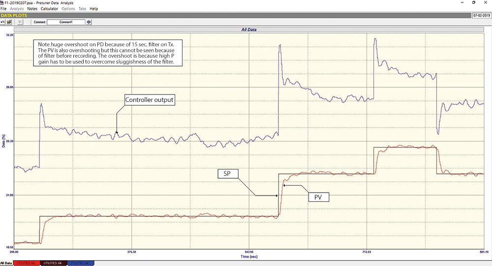
Figure 3 is the final closed loop test with tuning of P = 2,0 and I = 10 s/repeat and with the 6 s filter and dead band in the PLC’s controller removed. The test shows that the control is now working very much better.
Problems with large filters
It can be seen that on each of the SP changes, there is quite a large initial overshoot on the PD (controller output), whereas the PV came up to SP very nicely with no overshoot. This is interesting and shows one of the main problems that can be encountered when using a filter.
The problem is that because of the ‘sluggishness’ of the filter, which is very large for a flow process, the tuning requires a very high P gain to be inserted in the controller. Thus when you make the SP step change, the PD shoots up. This in turn opens the valve too far, which pushes the actual true process PV right up and the controller then reduces the PD back down to bring the PV into the right region. However, you don’t see the PV’s overshoot because the PV we see on our screen and on the recording has passed through the filter on the transmitter, so we don’t see and don’t know there has been a big overshoot.
The thing to remember is that filters, particularly large filters, can obscure what is happening in the actual process and this can be very dangerous in certain cases. I always suggest that it is far better for an operator to see what is actually happening in the process, rather than be left thinking everything is fine.
Unfortunately many operators are used to seeing highly filtered signals, so that when you remove the filters and they see the PV jumping around due to the noise, they believe that the process has gone unstable.
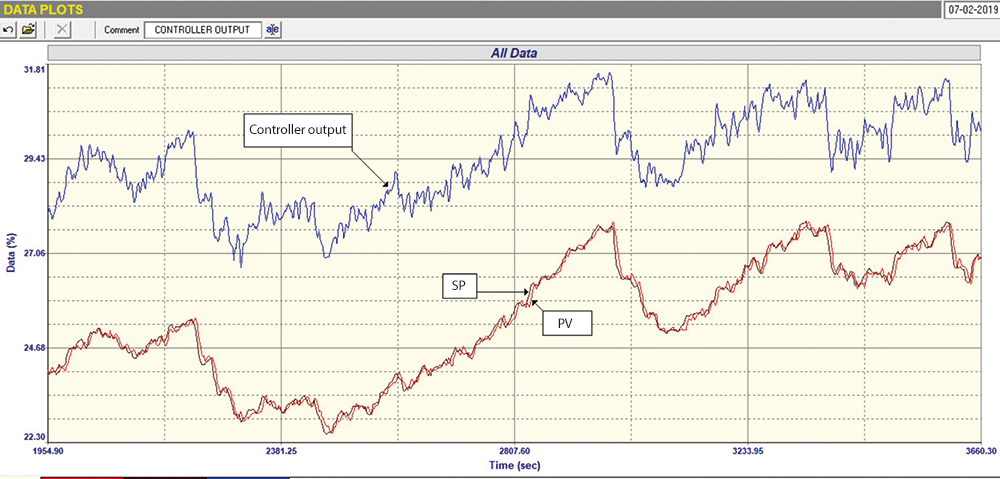
Figure 4 shows the control performance recorded over an hour with the control in cascade and the SP signal now coming from the output of the primary hydrogen pressure control loop. The remote SP is continuously changing and it can be seen just how well this secondary cascade flow loop is following. However, one should also be aware that as the transmitter filter had not been removed when this test was performed, the picture might well not have been as good as it looks here. There is no doubt that the filter should be removed and the loop retuned.
This serves as another good example to illustrate how lack of knowledge of the practicalities of control can result in terrible control characteristics.
About Michael Brown
Michael Brown is a specialist in control loop optimisation with many years of experience in process control instrumentation. His main activities are consulting, and teaching practical control loop analysis and optimisation. He gives training courses which can be held in clients’ plants, where students can have the added benefit of practising on live loops. His work takes him to plants all over South Africa and also to other countries. He can be contacted at Michael Brown Control Engineering cc,
| Email: | [email protected] |
| www: | www.controlloop.co.za |
| Articles: | More information and articles about Michael Brown Control Engineering |


© Technews Publishing (Pty) Ltd | All Rights Reserved
 printer friendly version