

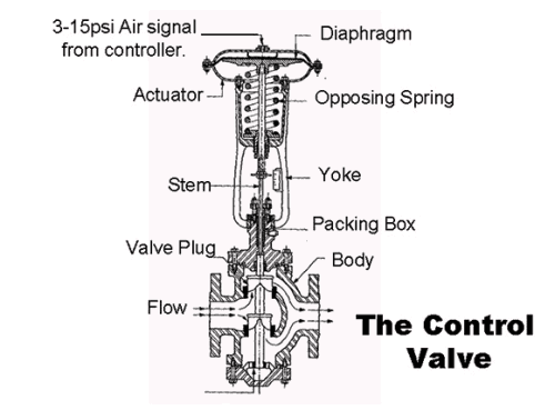
There are many types of final control elements including valves, dampers, feeders, louvres, and variable-speed drive devices, although, in general, the vast majority of final control elements found in the industrial control world are pneumatically actuated valves (typically as illustrated in Figure 1). It is impossible in this limited series of articles to go into great depth on all the various subjects and problems that can be encountered. What I am attempting to do here is to outline some of the practical problems, and some rules of thumb relating to final control elements, which can affect control in the real world. Most of the points specifically apply to pneumatically actuated valves, but may also be relevant to some other devices as well. It is also assumed that in the term ‘final control element’, we are referring to all the components involved, including the I/P (current-to-pneumatic) converter, air pressure regulators, valve actuator, the positioner, and the valve itself.
The actual purpose of the final control element is to regulate the flow of the process fluid strictly in accordance with the dictates of the controller output (PD). In other words, the valve must move to a position represented by the value of the PD. The faster and more accurately the valve follows these dictates, the better the control variance becomes.
The importance of the final control element cannot be overestimated. Many people mistakenly believe that the valve is not really critical to the control performance. Their thinking is that if the PD tells the valve to move to a particular position, and if the valve doesn’t get right to that point, then what does it matter? There is always the I (integral) term in the controller, the purpose of which is to eliminate control error, so if the valve doesn’t get to the right point then the controller will keep moving its output until the valve does actually get to the correct point.
This thinking sounds reasonable, but in reality it completely overlooks the time factor, and the fact that the integral influence is very small near setpoint (as will be discussed in the section on controllers at a later date in this series of articles). To give an example, a controller on a fast process (like flow), with a time constant of about 1 or 2 seconds, where the controller is tuned with fast integral, might take over 30 minutes to get a bad valve to the right position. On slow processes like temperature with time constants of many minutes or even longer, where the controller is tuned with slow integral, it may take the controller literally many hours to get the valve positioned correctly. One rule of thumb is that on slow processes, you cannot afford a poor valve if you want even half-reasonable control.
The majority of problems encountered in the control loop are to be found in the final control element. The reason for this is that – whereas other components in the modern loop like the measuring transmitter and controller are sophisticated devices, equipped with the latest technology from the fields of physics, electronics and computerisation, and generally with an absolutely minimum number of moving parts, if any at all – the valve in essence is a mechanical device where one ‘chunk’ of metal must be positioned accurately and repeatedly inside another ‘chunk’ of metal, often under extremely difficult process conditions of temperature, abrasion, stickiness, corrosion, pressure, etc. Any mechanical device is subject to all sorts of problems such as wear, various types of friction, repeatability, and rangeability.
The scale of the final control element problem
To give an idea of the problems encountered in typical industrial plants, a large South African petrochemical refinery optimised over 3000 control loops in its plant. The engineer in charge of this project reported that over 80% of the valves had to be worked on, or even replaced, before reasonable control could be achieved. One of the largest manufacturers of control valves in the world offers a service in the USA and Europe whereby they go into plants (using any make of valve) with computerised valve diagnostic equipment and give a report on the state of the valves. The head of the UK branch told me that, on average, the first time they go into a plant, they generally find between 70% and 75% of the valves in the plant have noticeable problems requiring correction if reasonable control is to be achieved.
There are many makes and types of control valves. A proper control valve specifically designed for modulating control purposes is an expensive device. Therefore, people often go for cheaper alternatives, typically using valves designed for manual operation, but fitted with an actuator, and sometimes a positioner. This can be sufficient for the control required, but the maxim remains: “If you want good control, you need a good valve.”
Valves, actuators and positioners
The chief feature of a good valve is that many years of research, design know-how and experience have been put into it by the manufacturer to make the valve perform properly. This performance will include accurate, repeatable positioning, generally as quickly as possible, under all the specified operating conditions. In addition, most manufacturers attempt to get the valve to respond to step changes as exponentially as possible. A little known fact is that in PID control, different tuning would in theory be needed for different sized step changes if the response is not exponential, as will occur for example on electrically actuated valves, which operate with a ramp response. (In reality, this is a minor problem, and would only have a real effect on very fast processes).
The use of a positioner on pneumatic actuated valves is essential. I have often come across people who believe that one should try and avoid positioners if possible. Typical thinking includes the belief that positioners cause instability, and that they shouldn’t ever be fitted to small valves, among others. However, a positioner is a must if you want good control. A reputable manufacturer will ensure that the positioner on the valve does not cause instability if set up properly.
A positioner does not, however, make up for an underpowered actuator. The actuator is the device that actually provides the motive power for the valve, not the positioner. The latter merely ensures that the actuator does move the valve to the correct point as given by the PD. On several occasions I have come across cases where people have tried to save money by fitting a smaller actuator because a positioner was fitted. This in fact creates an even more serious problem, which we have named ‘negative hysteresis’, and it will be described in another article in a few issues’ time.
The correct sizing of the valve is very important as it affects the process gain. This was discussed in a previous loop signature dealing with the importance of process gain. The valve sizing is itself of course established using a special formula.
From the process gain point of view, some general rules of thumb are that for practical purposes on self-regulating processes, the process gain should be between 0,5 and 2,0. In the case of integrating processes, the valve should be sized so that it is large enough to deal with the biggest load into (or out of, as the case may be) the process. At the same time, the valve should not be too large, so that under normal control conditions it will not operate too close to its seat.
This is an interesting point. If a valve operates close to seat under normal control conditions, apart from the fact that it is obviously oversized, many valves become very non-linear in low operating regions. A good guide is that the valve should under normal conditions operate at over the 20% open position, but some valve experts say that there should in fact be at least 20% of the actual flow through the valve. In the latter case, in the case of a valve with an equal percentage characteristic (see next article), it means that the valve position should be open past the 45% position.
The inherent rangeability of a control valve is the ratio of maximum controllable flow to minimum controllable flow. Typical figures for various classes of valves are:
• Globe valves: 10:1 to 30:1.
• V-notch ball: 100:1 to 300:1.
• Butterfly: 10:1 to 20:1.
• Sanders: 5:1.

It is of interest to note that even the best control valve does not have extremely wide rangeability, and if control is in fact required over a wide range of flows, then other strategies requiring more than one valve may be necessary. Control problems can result when the required rangeability exceeds the inherent rangeability of the final control element. Oversizing will of course reduce the inherent rangeability of the valve directly by the process gain.
Michael Brown
Michael Brown is a specialist in control loop optimisation with many years of experience in process control instrumentation. His main activities are consulting, and teaching practical control loop analysis and optimisation. He gives training courses which can be held in clients’ plants, where students can have the added benefit of practising on live loops. His work takes him to plants all over South Africa and also to other countries. He can be contacted at Michael Brown Control Engineering cc, +27 82 440 7790, [email protected], www.controlloop.co.za
| Email: | [email protected] |
| www: | www.controlloop.co.za |
| Articles: | More information and articles about Michael Brown Control Engineering |


© Technews Publishing (Pty) Ltd | All Rights Reserved
 printer friendly version